BECKHOFF M1110 User Manual
Page 14
M1110 Parallel Input / Output Box
Beckhoff II/O System
Page 14 of 17
Version 2.1
Date 09.03.93
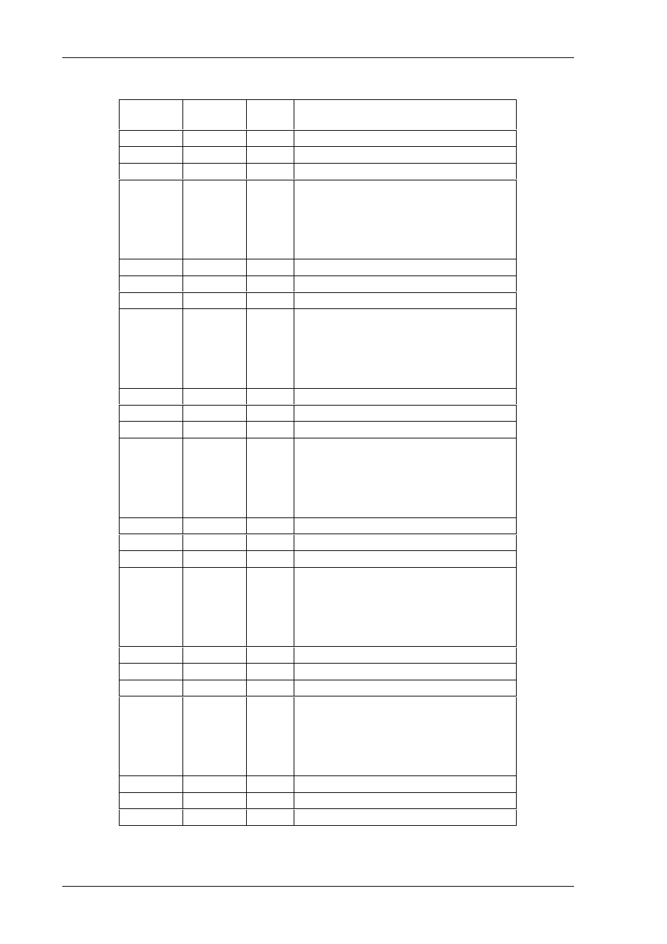
Signal Description
Pin
Signal
I/O
Description
D07-1
+24V
-
+24VDC support voltage
D07-2
n.c.
-
not connected
D07-3
GND
-
GND support voltage
D07-4
D0.7
I/O
Bit 7 of data byte 0
D0.7 is output,
if DIL_switch S1 = ON
D0.7 is input,
if DIL_switch S1 = OFF
D06-1
+24V
-
+24VDC support voltage
D06-2
n.c.
-
not connected
D06-3
GND
-
GND support voltage
D06-4
D0.6
I/O
Bit 6 of data byte 0
D0.6 is output,
if DIL_switch S1 = ON
D0.6 is input,
if DIL_switch S1 = OFF
D05-1
+24V
-
+24VDC support voltage
D05-2
n.c.
-
not connected
D05-3
GND
-
GND support voltage
D05-4
D0.5
I/O
Bit 5 of data byte 0
D0.5 is output,
if DIL_switch S1 = ON
D0.5 is input,
if DIL_switch S1 = OFF
D04-1
+24V
-
+24VDC support voltage
D04-2
n.c.
-
not connected
D04-3
GND
-
GND support voltage
D04-4
D0.4
I/O
Bit 4 of data byte 0
D0.4 is output,
if DIL_switch S1 = ON
D0.4 is input,
if DIL_switch S1 = OFF
D03-1
+24V
-
+24VDC support voltage
D03-2
n.c.
-
not connected
D03-3
GND
-
GND support voltage
D03-4
D0.3
I/O
Bit 3 of data byte 0
D0.3 is output,
if DIL_switch S1 = ON
D0.3 is input,
if DIL_switch S1 = OFF
D02-1
+24V
-
+24VDC support voltage
D02-2
n.c.
-
not connected
D02-3
GND
-
GND support voltage