9 usb 1 to 4, lan, sound, Aution – BECKHOFF CB4050 User Manual
Page 28
Chapter: Connectors
USB 1 to 4, LAN, Sound
page 28
Beckhoff New Automation Technology CB4050
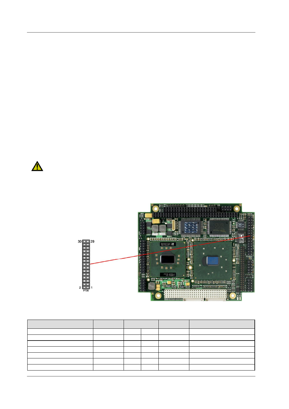
4.9 USB 1 to 4, LAN, Sound
USB 1-4, LAN and sound are provided via a standard IDC socket connector with a spacing of 2.54 mm.
Necessary settings can be accomplished in BIOS setup.
All USB-channels support USB 2.0. You may note that the setting of USB keyboard or USB mouse
support in the BIOS-setup is only necessary and advisable, if the OS offers no USB-support. BIOS-setup
can be changed with a USB keyboard without enabling USB keyboard support. Running a USB
supporting OS (such as Microsoft® Windows®) with these features enabled may lead to significant
performance or functionality limitations.
Every USB interface provides up to 500 mA current and is protected by an electronically resettable fuse.
The LAN-interface on this connector supports 10BaseT and 100BaseT compatible network components
with automatic bandwidth selection. Additional outputs are provided for status LEDs. Auto-negotiate and
auto-cross functionality is available, PXE and RPL are available on request.
AC'97 - 2.3 compatible audio I/O is available on this connector. There are two ways to use these signals.
Default functionality is the familiar audio in, audio out, and microphone (2-channel mode). OS dependent
device drivers can switch these signals to support an 5.1 output; thus in this mode no audio input signals
are available. In 2-channel mode LOUT is the only active audio output. Moth MIC inputs are available. In
6-channel mode the speaker outputs are: LOUT to Front, AUXA to Surround, MIC1 to Center and MIC2 to
LFE (Sub).
The signals "SPDIFI" and "SPDIFO" provide digital input and output. If a transformation to a coaxial or
optical connector is necessary this must be performed externally.
C
AUTION
The same IDC socket connector supports all three devices and is not "keyed"! Misconnected support
cables may short two devices together and damage the board. Please check diagrams before installing
any connecting cables to ensure proper connection.
Description
Name
Pin
Name
Description
5 volt for USB1
USB1 VCC
1
2
USB2 VCC
5 volt for USB2
USB- channel 1
USB1#
3
4
USB2#
USB- channel 2
USB+ channel 1
USB1
5
6
USB2
USB+ channel 2
ground
GND
7
8
GND
ground
USB+ channel 3
USB3
9
10
USB4
USB+ channel 4
USB- channel 3
USB3#
11
12
USB4#
USB- channel 4
5 volt for USB3
USB3 VCC
13
14
USB4 VCC
5 volt for USB4