Optimisation – speed control using the kl2791 – BECKHOFF DK9222-1009-0006 User Manual
Page 4
I/O
Bus Terminal
Application Note DK9222-1009-0006
This publication contains statements about the suitability of our products for certain areas of application. These statements are based on typical features of our products. The examp-
les shown in this publication are for demonstration purposes only. The information provided herein should not be regarded as specific operation characteristics. It is incumbent on the
customer to check and decide whether a product is suit-able for use in a particular application. We do not give any warranty that the source code which is made available with this
publication is complete or accurate. This publication may be changed at any time with-out prior notice. No liability is assumed for errors and/or omissions. Our products are described
in detail in our data sheets and documentations. Product-specific warnings and cautions must be observed. For the latest version of our data sheets and documentations please visit
our website (www.beckhoff.com).
© Beckhoff Automation GmbH, October 2009
The reproduction, distribution and utilisation of this document as well as the communication of its contents to others without express authorisation is prohibited. Offenders will be
held liable for the payment of damages. All rights reserved in the event of the grant of a patent, utility model or design.
Optimisation – speed control using the KL2791
In neither case the power consumption of the pump is affected; therefore, the use of the single-phase AC motor terminal makes
sense in order to achieve a reduction in the consumed power.
5
4
2
1
3
KL2791
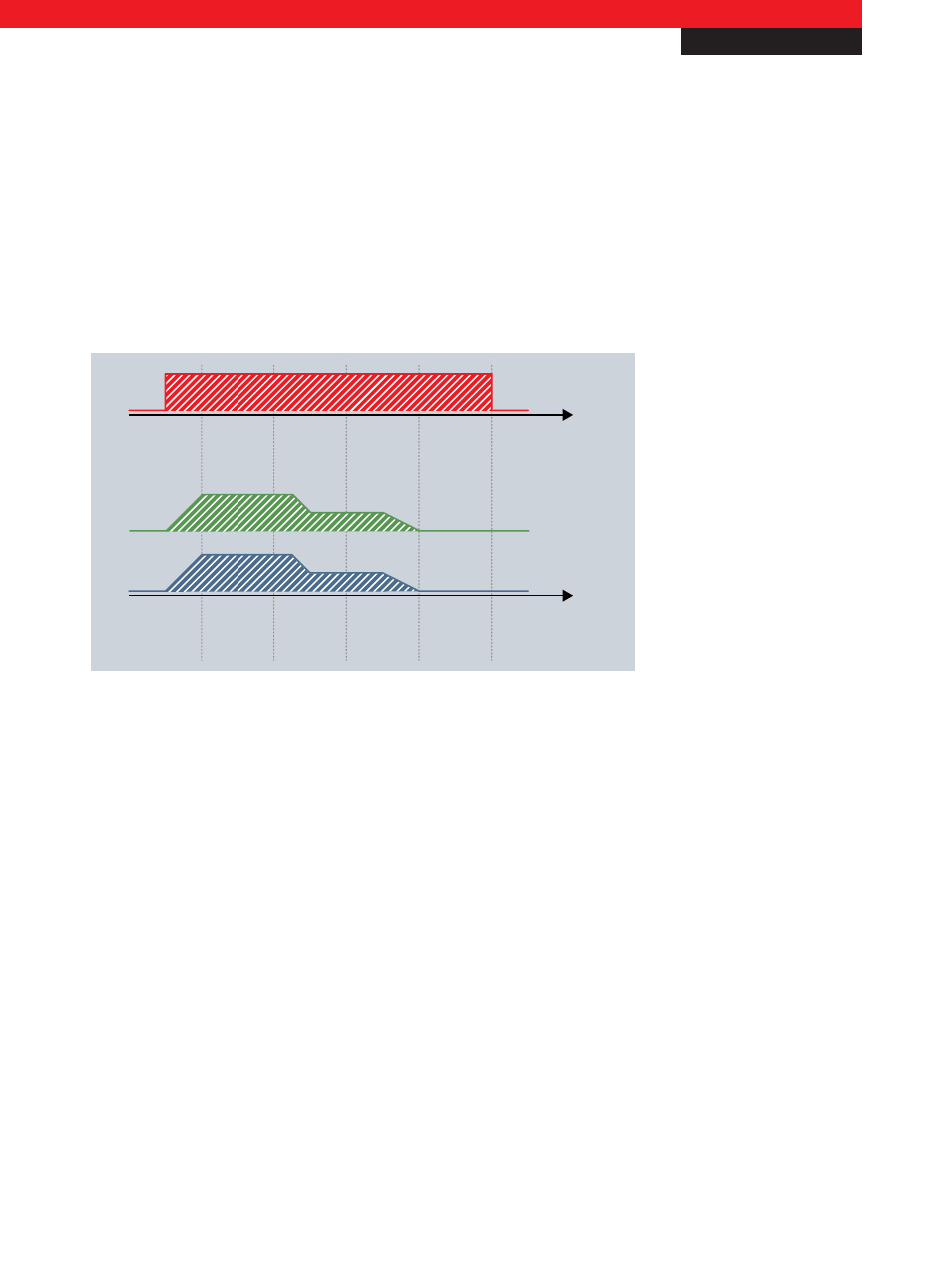
Volume rate of flow
Pump
Start-up
phase
1
st
cut
Constant
cut
Exit
Move-out
phase
Tool drive active
Cooling lubricant consumption
Energy consumption
Fig. 4 Optimised control with the KL2791
Using the KL2791 single-phase AC motor terminal, a single-phase AC motor with a maximum power consumption of 0.1 kW
can be operated with speed control depending on the process data. L1 and N of the motor are wired directly to the terminal;
this is in turn integrated in the control environment via a Bus Coupler or connected directly to an embedded device.
The controller specifies the set value for the motor speed in the form of a 16-bit word; the speed is regulated internally in the
terminal: the motor is switched on and off with a practice-proven mains-synchronous pattern, so that the motor consumes less
power and the speed falls significantly. This method is well suited to motors with fixed loads, such as pumps and fans, in order
to achieve a control range for the flow rate from 10 % to 100 %.
– 1-channel AC motor speed controller, 230 V AC, 100 VA www.beckhoff.com/KL2791
– The modular fieldbus system for automation www.beckhoff.com/Busterminal
New Automation Technology
Beckhoff
4