Scenario 1 – BECKHOFF DK9222-1009-0006 User Manual
Page 2
I/O
Bus Terminal
Application Note DK9222-1009-0006
When driving working machines whose production or conveying output can be influenced via the drive speed of the motor,
energy can be saved by means of variable speed. This particularly applies if the change in the motor speed is also linked with
large changes in the emitted mechanical output. Increase the speed – higher load, decrease – lower load. This procedure is
particularly suitable for uncontrolled units with a square load characteristic, because regulating the speed just a little brings
about a large change in energy consumption due to its square influence.
Practical example
Cooling lubricant pump in a milling machine
Two frequently occurring control scenarios are illustrated here, after which the optimisation is demonstrated. The pump is
coupled in both cases to the tool drive in order to guarantee that sufficient cooling lubrication takes place when the blades cut
into the workpiece.
Scenario 1
5
4
2
1
3
Scenario 1
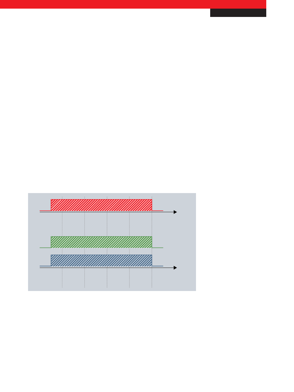
Volume rate of flow
Pump
Start-up
phase
1
st
cut
Constant
cut
Exit
Move-out
phase
Tool drive active
Cooling lubricant consumption
Energy consumption
Fig. 2 Need for optimised control
Cooling lubrication is fundamentally required during the runtime of the miller (tool drive) in order to achieve appropriate
surface qualities and to keep the thermal loading of the workpiece low. For this reason, the cooling lubricant circulation pump
is linked to the tool drive in order to securely guarantee pumping. There are two operating cases for the pump: Pump on | pump
off; therefore, no changes in the load take place. The pump always runs at full speed and with full power consumption, even
during the phases where the tool is moving in and moving out (1 and 5), at which time the tool drive is active, but the tool
itself is not cutting.
New Automation Technology
Beckhoff
2
For application notes see disclaimer on the last page