BECKHOFF KL5111-0000 User Manual
Page 12
Register description
10
KL5111-0000
R10: Data length
R10 contains the number of multiplexed shift registers and their length in bits. The bus coupler sees this
structure.
R11: Signal channels
In comparison with R10, the number of logically existing channels is located here. For example, one
physically existing shift register may consist of several signal channels.
R12: Minimum data length
The respective byte contains the minimum data length of a channel to be transferred. If the MSB is set,
then the control/status byte is not necessarily needed for the function of the terminal and, with appropriate
configuration of the coupler, is not transferred to the control system.
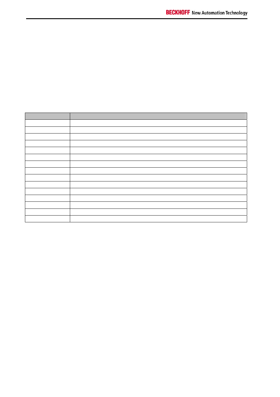
R13: Data type register
Data type
Description
0x00
Terminal without valid data type
0x01 Byte
array
0x02
Structure 1 Byte, n Bytes
0x03 Word
array
0x04
Structure 1 Byte, n Words
0x05 Double
word
array
0x06
Structure 1 Byte, n Double words
0x07
Structure 1 Byte, 1 Double word
0x08
Structure 1 Byte, 1 Double word
0x11
Byte a with a variable logical channel length
0x12
Structure 1 Byte, n Bytes with variable logical channel length (e.g. 60xx)
0x13
Word-Array with a variable logical channel length
0x14
Structure 1 Byte, n Words with a variable logical channel length
0x15
Double word -Array with a variable logical channel length
0x16
Structure 1 Byte, n Double words with a variable logical channel length
R14: not used
R15: Alignment-Bits (RAM)
The analog terminal is set to a byte limit in the terminal bus with the alignment bits.