Annex, Mapping in the bus coupler – BECKHOFF KL5051 User Manual
Page 15
Annex
KL5051
15
Annex
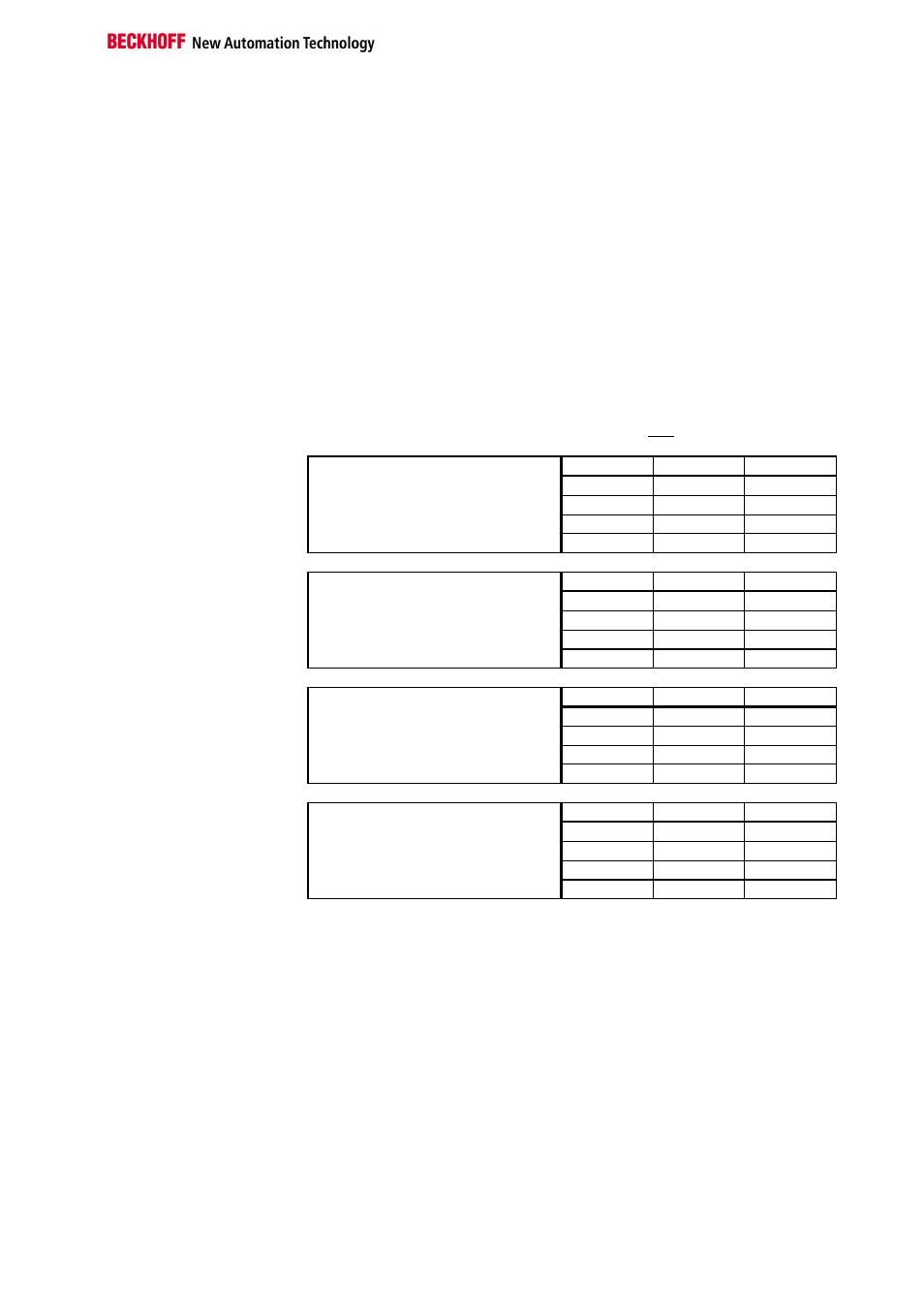
As already described in the chapter terminal configuration, each bus termi-
nal is mapped in the bus coupler. In the standard case, this mapping is
done with the default setting in the bus coupler / bus terminal. This default
setting can be modified with the Beckhoff KS2000 configuration software or
using master configuration software (e.g. ComProfibus or TwinCAT System
Manager). The following tables provide information on how the KL5051
maps itself in the bus coupler depending on the set parameters.
Mapping in the bus coupler
Standard Format
The KL5051 is mapped in the bus coupler depending on the set parame-
ters. The terminal is always evaluated completely, the terminal occupies
memory space in the process image of the input and outputs.
I/O Offset
High Byte
Low Byte
Complete evaluation
= X
3
MOTOROLA format
= 0
2
D5
D4
Word alignment
= 0
1
CT/ST-3
D2
Default: CANCAL,
CANopen, RS232,
RS485, ControlNet,
DeviceNet
0
D1
CT/ST-0
I/O Offset
High Byte
Low Byte
Complete evaluation
= X
3
MOTOROLA format
= 1
2
D4
D5
Word alignment
= 0
1
CT/ST-3
D1
Default: Interbus,
Profibus
0
D2
CT/ST-0
I/O Offset
High Byte
Low Byte
Complete evaluation
= X
3
D5
D4
MOTOROLA format
= 0
2
-
CT/ST-3
Word alignment
= 1
1
D2
D1
Default: Lightbus,
Bus Terminal Controller
(BCxxxx)
0
-
CT/ST-0
I/O Offset
High Byte
Low Byte
Complete evaluation
= X
3
D4
D5
MOTOROLA format
= 1
2
-
CT/ST-3
Word alignment
= 1
1
D1
D2
0
-
CT/ST-0
Legend
Complete evaluation: The terminal is mapped with control / status byte.
Motorola format: The Motorola or Intel formal can be set.
Word alignment: The terminal is at a word limit in the bus coupler.
CT-0(A0): Control- Byte (appears in the PI of the outputs).
ST-0(E0): Status- Byte (appears in the PI of the inputs).
CT-3(A3): Control- Byte (appears in the PI of the outputs).
ST-3(E3): Status- Byte (appears in the PI of the inputs).
D1, D2, D4, D5 = A1, E1, A2, E2, A4, E4, A5, E5