BECKHOFF KL5001 User Manual
Page 7
Terminal configuration
KL5001
7
Profibus coupler BK3000
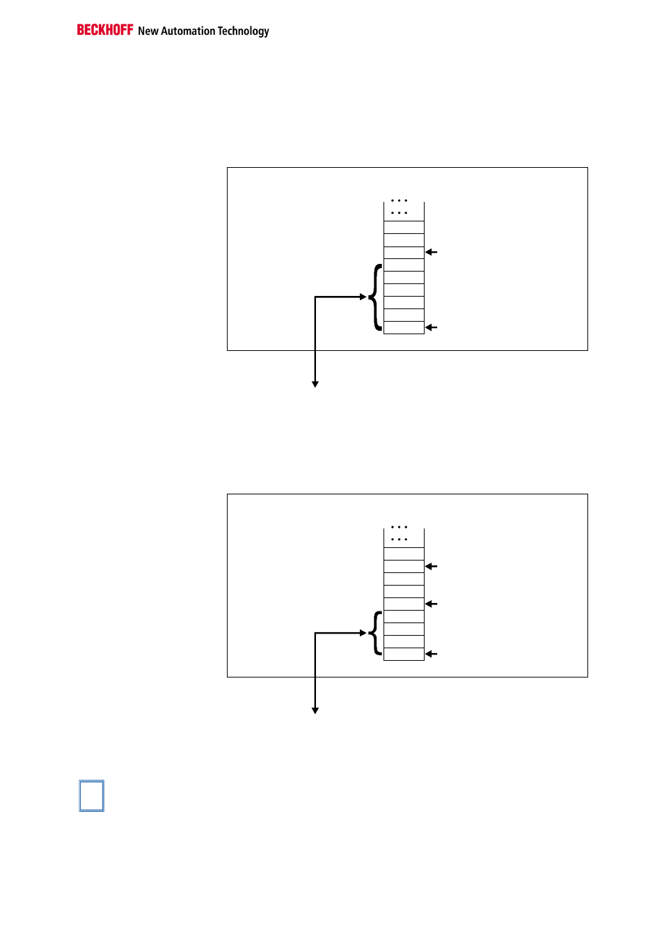
In the case of the Profibus coupler BK3000, for which terminal channels
the control/status byte is also to be inserted must be defined in the master
configuration. If the control/status byte is not evaluated, the KL5001 occu-
pies 4 bytes of input data. The figure shows the mapping with con-
trol/status byte.
Offset Terminal1 Channel1 = 0
KL5001
Offset Terminal2 Channel1 = 6
The control/status byte
must be inserted for
parameterization.
K-Bus
Profibus bus coupler
BK3000
T othe bus terminal
D3
D2
D0
-
D1
Data H
Data L
Data L
C/S
0
The terminal is
mapped in the
bus coupler.
Interbus coupler BK4000
By default, the Interbus coupler BK4000 maps the Kl5001 with 4 bytes of
input data. Parametrization via the field bus is not possible. The KS2000
software is required for configuration if use is to be made of the con-
trol/status byte.
Offset Terminal1 Channel1 = 0
Offset Terminal2 Channel1 = 4
KL5001
Offset Terminal2 Channel2 = 7
The control/status byte
must be inserted for
parameterization (KS2000).
K-Bus
Interbus bus coupler
BK4000
To the bus terminal
Data H
Data H
Data H
Data L
D1
D0
D3
D2
Nutz L
0
The terminal is
mapped in the
bus coupler.
Other bus couplers and
further information
You will find further information on the mapping configuration of bus cou-
plers in the annex of the respective bus coupler manual and under the
heading of "Configuration of Masters".
i
Note
The annex contains an overview of possible mapping configurations de-
pending on the parameters that can be set.
Parameterization with
the KS2000 software
Independently of the field bus system, parameters can be set via the serial
configuration interface in the bus coupler using the Beckhoff KS2000 con-
figuration software.