Description of functions, Terminal configuration, The terminal is mapped in the bus coupler – BECKHOFF KL5001 User Manual
Page 6
Description of functions
6
KL5001
Description of functions
The terminal KL5001 is an SSI interface for the direct connection of an SSI
sensor. The sensor is powered via the SSI interface. To read out the sen-
sor, the terminal outputs a clock burst and provides the incoming data stre-
am to the controller in the process image. Different operating modes,
transmission frequencies, bit widths and code conversions can be set. The
individual configuration is stored permanently in a register set.
LED display
The run LED indicates the operating state of the terminal.
On – normal operation
Off – watchdog timer overflow has occurred. The green LED goes off if no
process data is transmitted by the bus coupler for 100 ms.
Process data
Alternative output format
The SSI interface is supplied with a data width of 24 bits and Gray binary
number conversion activated in the alternative output format. The baud
rate to the SSI sensors is set to 250 kHz. The process data is output in the
input data bytes D0 - D3. Mapping of the terminal in the alternative format
is described in further detail in the chapter on terminal configuration.
Standard output format
In the standard output format, 4 bytes of input data are mapped in the bus
coupler by default.
Terminal configuration
The terminal can be configured and parameterized via the internal register
structure.
Each terminal channel is mapped in the bus coupler. The data of the termi-
nal is mapped differently in the memory of the bus coupler depending on
the type of the bus coupler and on the set mapping configuration (e.g. Mo-
torola/ Intel format, word alignment,...). For parameterization of a terminal,
the control/status byte must also be mapped.
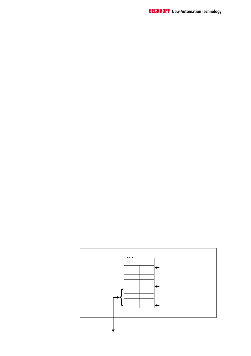
Beckhoff Lightbus
coupler BK2000
In the case of the Beckhoff Lightbus coupler BK2000, the control /status
byte is also always (i.e. in the case of all analog terminals) mapped in addi-
tion to the data bytes. It is always in the low byte at the offset address of
the terminal channel.
0
Offset Terminal1 Channel1 = 0
Offset Terminal2 Channel1 = 4
KL5001
Offset Klemme 2 Kanal 2 = 8
User dat allocation depending
on mapping
K-Bus
Beckhoff-Lightbus
bus coupler
BK2000
To the bus terminal
L
H
C/S
D0
D2
Data L
Data H
Data H
Data L
-
-
-
D1
D3
C/S
C/S
C/S
The terminal is
mapped in the
bus coupler