BECKHOFF KL1512 User Manual
Page 7
Terminal configuration
KL1512
5
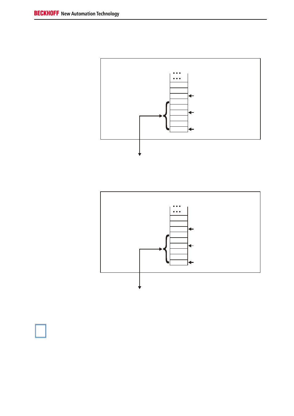
Profibus coupler BK3000
When using the Profibus coupler BK3000, the KL1512 is automatically
mapped with 6 bytes of input data and 6 bytes of output data.
Offset Terminal1 Channel1 = 0
Offset Terminal1 Channel2 = 3
Offset Terminal2 Channel1 = 6
KL 1512 Channel 1
KL 1512 Channel 2
The control-/status byte
must be inserted for
parameterization.
K-Bus
Profibus bus coupler
BK3000
To the bus terminal
Data H
Data L
D1 - 0
D0 - 0
D0 - 1
D1 - 1
C/S - 0
C/S
C/S - 1
0
The terminal is
mapped in the
bus coupler.
Interbus coupler BK4000
When using the Interbus coupler BK4000, the KL1512 is automatically
mapped with 6 bytes of input data and 6 bytes of output data.
Offset Terminal1 Channel1 = 0
Offset Terminal1 Channel2 = 3
Offset Terminal2 Channel1 = 6
KL 1512 Channel 1
KL 1512 Channel 2
The control-/status byte
must be inserted for
parameterization.
K-Bus
Profibus bus coupler
BK3000
To the bus terminal
Data H
Data L
D1 - 0
D0 - 0
D0 - 1
D1 - 1
C/S - 0
C/S
C/S - 1
0
The terminal is
mapped in the
bus coupler.
Other bus couplers and
further information
You will find further information on the mapping configuration of bus
couplers in the annex of the respective bus coupler manual under the
heading of Configuration of masters.
i
Note
In the appendix it exists an outline of the possible mapping configurations
in dependency of the adjustable parameters.
Parameterization with the
KS2000 software
Using the KS2000 configuration software, the parameterization operations
can be carried out independently of the field bus system via the bus
couplers serial interface.