Beckhoff lightbus bus coupler bc2000 – BECKHOFF BC2000 User Manual
Page 7
Basic Principles
BC2000
6
Display of the channel state
functions limits the number of unused channels to a maximum of one per
function. The presence of two channels in one terminal is the optimum
compromise of unused channels and the cost of each channel. The
possibility of galvanic isolation through potential feed terminals also helps
to keep the number of unused channels low.
The integrated LEDs show the state of the channel at a location close to
the sensors and actuators.
K bus
End terminal
Potential feed terminals for
galvanically isolated groups
The terminal bus (known as the K bus) is the data path within a terminal
strip. The terminal bus is led through from the bus terminal controller
through all the terminals via six contacts on the terminals‘ side walls. The
end terminal terminates the terminal bus. The user does not have to learn
anything about the function of the terminal bus or about the internal
workings of the terminals and the bus terminal controller. Many software
tools that can be supplied make project planning, configuration and
operation easy.
The operating voltage is passed on to following terminals via three power
contacts. You can divide the terminal strip into arbitrary galvanically
isolated groups by means of potential feed terminals. The feed terminals
play no part in the control of the terminals, and can be inserted at any
points within the terminal strip.
Up to 64 terminals can be used within one terminal strip;
Potential feed terminals and end terminals are included in this count.
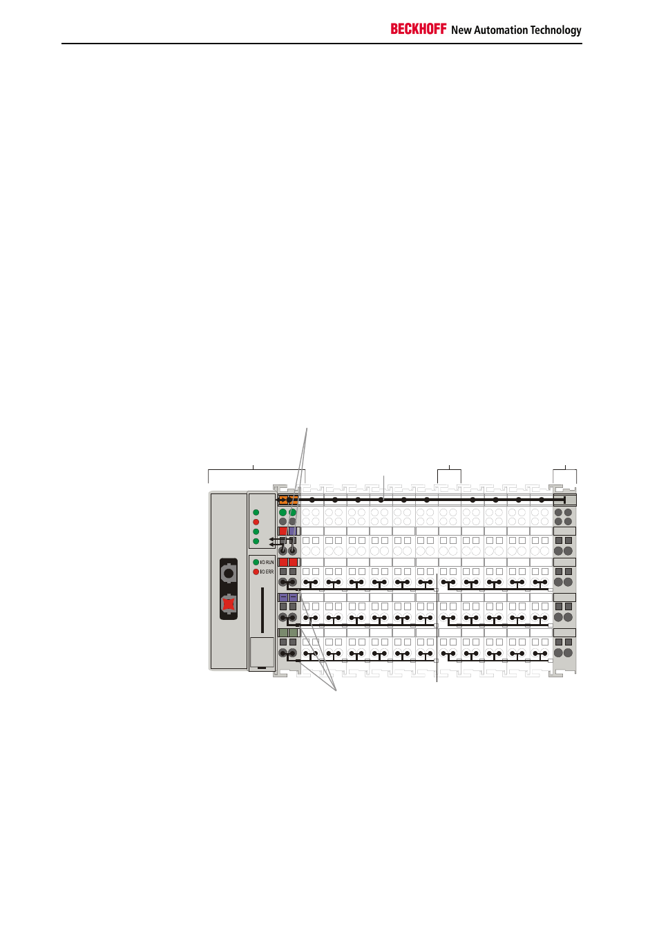
The principle of the
bus terminal
02
01
+
+
PE PE
B
E
C
K
H
O
FF
24V
0V
Terminal bus
End terminal
Galvanic
isolation
Potential
feed
terminal
Power
contacts
Supply voltage
for the
bus coupler
CYC
ERR
WD
II/O-Lightbus
Beckhoff Lightbus
bus coupler
BC2000
B
C
20
0
0
PLC
Additional characteristics of
the bus terminal controllers
The bus terminal controller (BC) differs from the bus coupler (BK) in that in
addition to operating the terminal bus, a PLC task runs in the BC2000.
Unlike bus couplers, the signals from the terminals are processed by the
PLC task, while the fieldbus carries the in- and outputs of the PLC task.
It is also possible to partition the terminals in such a way that some of the
terminals are processed by the PLC task while others are passed over the
fieldbus to a master.