BECKHOFF BK2000 User Manual
Page 25
Annex
BK2000
25
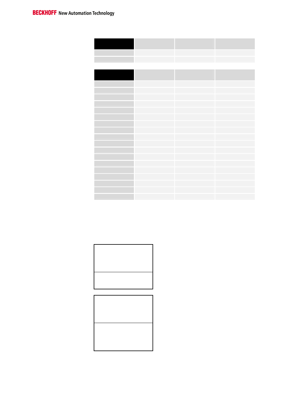
Part for byte-oriented
data, analog inputs
Relative byte
address
Bit position
Process image in
the controller
Position in the
block
0, 1, 3, 4
none
E0, E1, E2
POS10
5, 6, 7, 8
none
E3, E4, E5
POS13
Part for non-byte-oriented
data, digital inputs
Relative byte
address
Bit position
Process image in
the controller
Position in the
block
9
0
E6
POS01
9
1
E6
POS01
9
2
E6
POS02
9
3
E6
POS02
9
4
E6
POS03
9
5
E6
POS03
9
6
E6
POS04
9
7
E6
POS04
10
0
E7
POS05
10
1
E7
POS05
10
2
E7
POS06
10
3
E7
POS06
10
4
E7
POS15
10
5
E7
POS15
10
6
E7
POS16
10
7
E7
POS16
11
0
E8
POS17
11
1
E8
POS17
The positions POS14 and POS21 are not relevant in relation to the
exchange of data. They do not appear in the list. If a byte, e.g. E11, is not
used completely, the bus coupler pads the remaining bits of the byte with
zeros.
Overview of the breakdown of the process image in the bus coupler:
Output data in the
bus coupler
A0
...
byte-oriented data
...
A24
A25
bit-oriented data
A26
Input data in the
bus coupler
E0
...
byte-oriented data
...
E8
E9
...
bit-oriented data
...
E11
The base addresses E0 and A0 listed here are relative addresses or
addresses in the bus coupler. Depending on the higher-level field bus, the
addresses may be placed in a freely chosen position in the controller's
process image by the bus master. The master's configuration software