BECKHOFF BK2000 User Manual
Page 11
Basic information
BK2000
11
Insulation test
PE power contacts
The connection between bus couplers and bus terminals is automatically
effected by latching the components together. The K-bus is responsible for
passing data and power to the electronic components of the bus terminals.
In the case of digital bus terminals, the field logic receives power via the
power contacts. Latching the components together has the effect that the
series of power contacts constitutes a continuous power track. Please refer
to the circuit diagrams of the bus terminals: some bus terminals do not loop
these power contacts through, or not completely (e.g. analog bus terminals
or 4-channel digital bus terminals). Each power input terminal interrupts the
series of power contacts and constitutes the beginning of a new track. The
bus coupler can also be used to supply power to the power contacts.
The power contact labeled “PE” can be used as protective earth or ground.
This contact stands proud for safety reasons and can carry short-circuit
currents of up to 125A. Note that in the interests of electromagnetic
compatibility the PE contacts are capacitively connected to the supporting
track. This may lead to spurious results and even damage to the terminal
when you test the insulation (e.g. insulation test for breakdown using a
230V mains supply to the PE line). You should therefore disconnect the PE
line on the bus coupler while you carry out insulation tests. You can
disconnect other power supply points for the duration of the test by drawing
the power supply terminals out from the remaining row of terminals by at
least 10mm. If you do this, there will be no need to disconnect the PE
connections.
The protective earth power contact (“PE”) may not be used for any other
connections.
Electrical data
Lightbus couplers may have different configuration levels. The electrical
data specific to the fieldbus is listed in the appropriate chapter. The
following data distinguishes between the standard version and the
economy version (BK2000 and BK2010). Either version is fully compatible
to the Beckhoff-Lightbus, but the economy version has only a limited
number of I/O points, which is why it permits you to attach only digital
inputs and outputs.
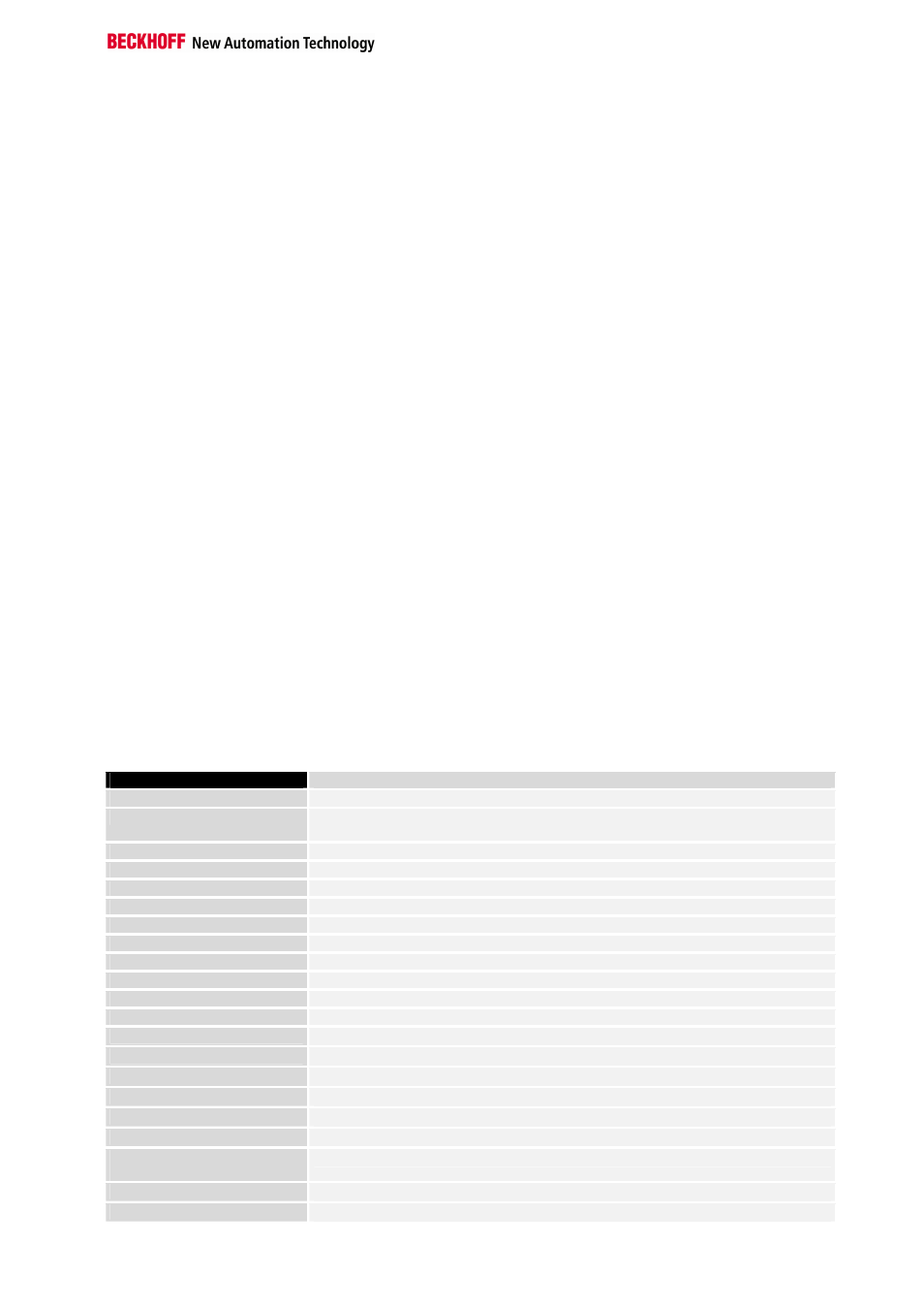
Technical data
Beckhoff-Lightbus coupler BK2000
Economy coupler BK2010
Voltage supply
24 V, + / - 10%
Input current
105 mA typical
85 mA typical
900 mA max.
300 mA max.
Output current K-bus
1.75 A max.
0.5 A max.
Supply isolation
500 Veff (K-bus / supply voltage)
Number of bus terminals
64
Digital peripheral signals
256 inputs and outputs
256 inputs and 256 outputs
Analog peripheral signals
128 inputs and outputs
--
Peripheral bytes
512 input and 512 output bytes
32 input and 32 output bytes
Configuration interface
Available for KS2000
Baud rates
2,5 MBaud
Voltage power contact
24V DC / AC
Current load power con.
10 A
Max. voltage capacity
500 Veff (power contact / supply voltage)
Weight approx.
150g
130g
Operating temperature
0°C ... +55°C
Storage temperature
-25°C ... +85°C
Relative humidity
95% non-condensing
Vibration /shock resistance
according to IEC 68-2-6 / IEC 68-2-27
Interference resistance.
Burst / ESD
according to EN 61000-4-4/ EN 61000- 4-, limit EN 50082-2-4
Orientation for mounting
any
Type of fuse
IP20