Annex – BECKHOFF BK2000 User Manual
Page 24
Annex
24
BK2000
Annex
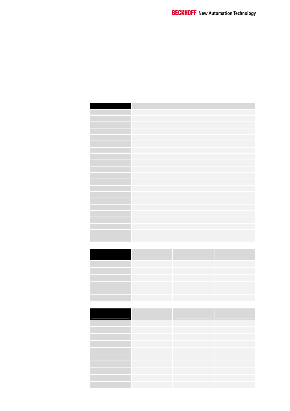
Example: combination of a process image
in the bus coupler
An example explains how the input and output channels are allocated to
the process image. The example setup will consist of the following bus
terminal modules:
The bus coupler creates
Position
Function module on the rail
the following allocation
POS01
Bus coupler
list with this configuration
POS02
Digital inputs, 2 channels
POS03
Digital inputs, 2 channels
POS04
Digital inputs, 2 channels
POS05
Digital inputs, 2 channels
POS06
Digital inputs, 2 channels
POS07
Digital outputs, 2 channels
POS08
Digital outputs, 2 channels
POS09
Digital outputs, 2 channels
POS10
Analog inputs, 2 channels
POS11
Analog outputs, 2 channels
POS12
Analog outputs, 2 channels
POS13
Analog inputs, 2 channels
POS14
Infeed terminal
POS15
Digital inputs, 2 channels
POS16
Digital inputs, 2 channels
POS17
Digital inputs, 2 channels
POS18
Digital outputs, 2 channels
POS19
Digital outputs, 2 channels
POS20
Analog outputs, 2 channels
POS21
End terminal
Part for byte-oriented
data, analog outputs
Relative
byte address
Bit position
Process image in
the controller
Position in the
block
0, 1, 3, 4
none
A0, A1, A2
POS11
5, 6, 7, 8
none
A3, A4, A5
POS11
9, 10, 11, 12
none
A6, A7, A8
POS12
13, 14, 15, 16
none
A9, A10, A11
POS12
17, 18, 19, 20
none
A12, A13, A14
POS20
21, 22, 23, 24
none
A15, A16, A17
POS20
Part for non-byte-oriented
data, digital outputs
Relative byte
address
Bit position
Process image in
the controller
Position in the
block
25
0
A18
POS07
25
1
A18
POS07
25
2
A18
POS08
25
3
A18
POS08
25
4
A18
POS09
25
5
A18
POS09
25
6
A18
POS18
25
7
A18
POS18
26
0
A19
POS19
26
1
A19
POS19