Xs01 – BECKHOFF CP790x-140x User Manual
Page 15
Product Description
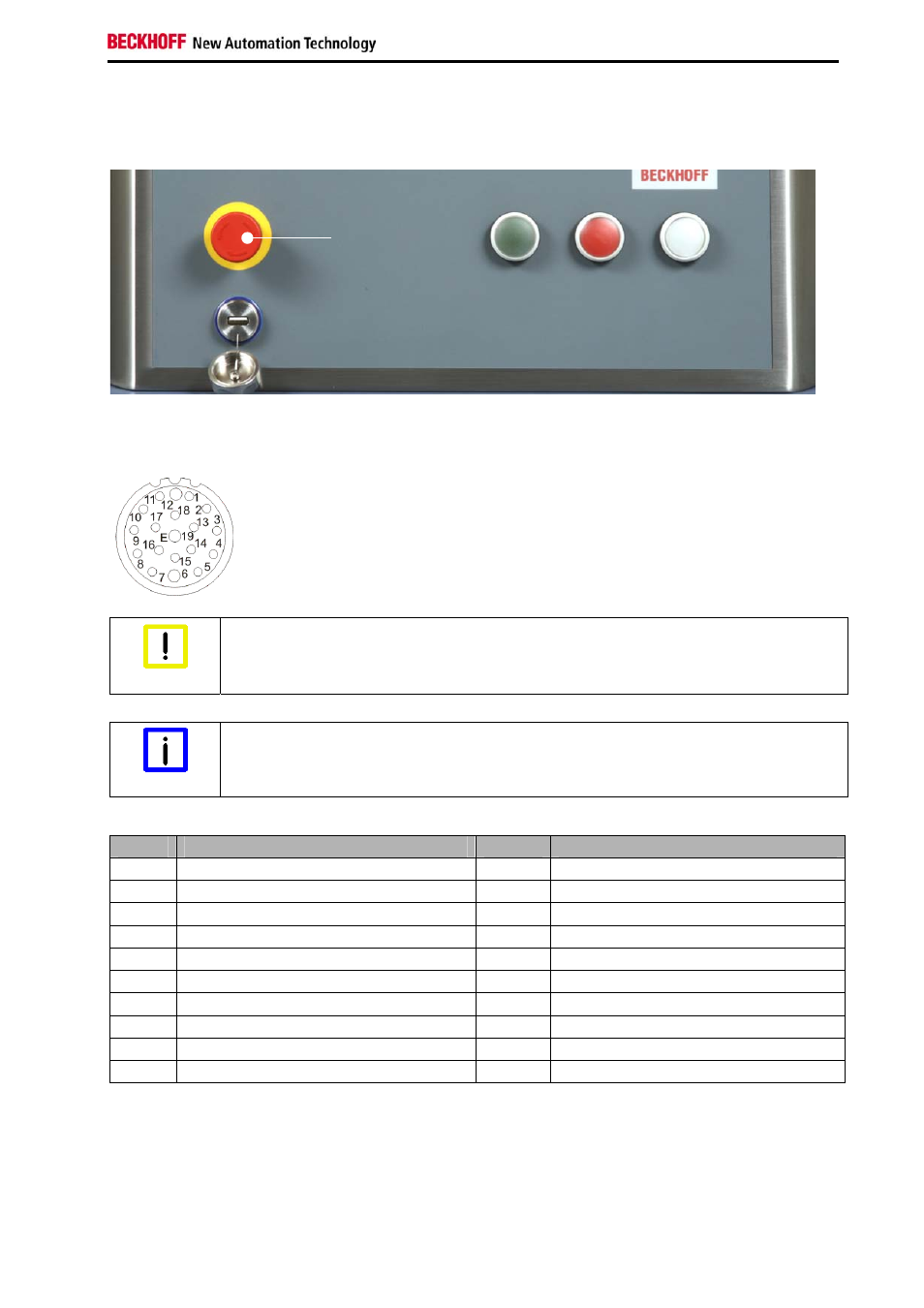
2.4.5 Connection Emergency stop and push-buttons CP790x-1401 (XS01)
In the front of the Control Panel CP790x-1401, an emergency stop button (S1) and three
electromechanical push-buttons (S2 - S4) are integrated. The buttons can be connected user-specific.
emergency stop
button (S1)
push-
button S2
push-
button S3
push-
button S4
The connection of the emergency stop button and the electromechanical push-buttons are established via
the 19-pole M20 (XS01) connector in the connection area. The protection class of the circular plug-in
connector accords to the IP67-standard. For the accurate connection see chapter
XS01
Circular plug-in connector 19-pole M20 built-in linear, IP67, Intercontec
(Intercontec A EG A 378 MR93 00 0032 000)
Take notice of the ampacity
Warning
The maximum ampacity of the pin for connecting the emergency stop button and the
electromechanical push-buttons is 100 mA at max. 35 V AC/ DC.
Male connector is provided
Note
The male connector Intercontec A ST A 278 FR91 61 0035 000 is provided with the
Control Panel.
Pin
Signal
Pin
Signal
1
S1.12
11
LED red K1
2 S1.11
12 PE
3 S1.22
13 S4.14
4 S1.21
14 S4.22
5
S2.14
15
LED white K1
6 GND
16 NC
7 S2.22
17 NC
8
LED green K1
18
NC
9 S3.14
19 +
24V
10 S3.22
CP790x-140x
13