Operating instructions, Configuration, Dip switch 1 (sw1) – BECKHOFF CU8810-0000 User Manual
Page 11: Configuration 9
Operating Instructions
Operating Instructions
Configuration
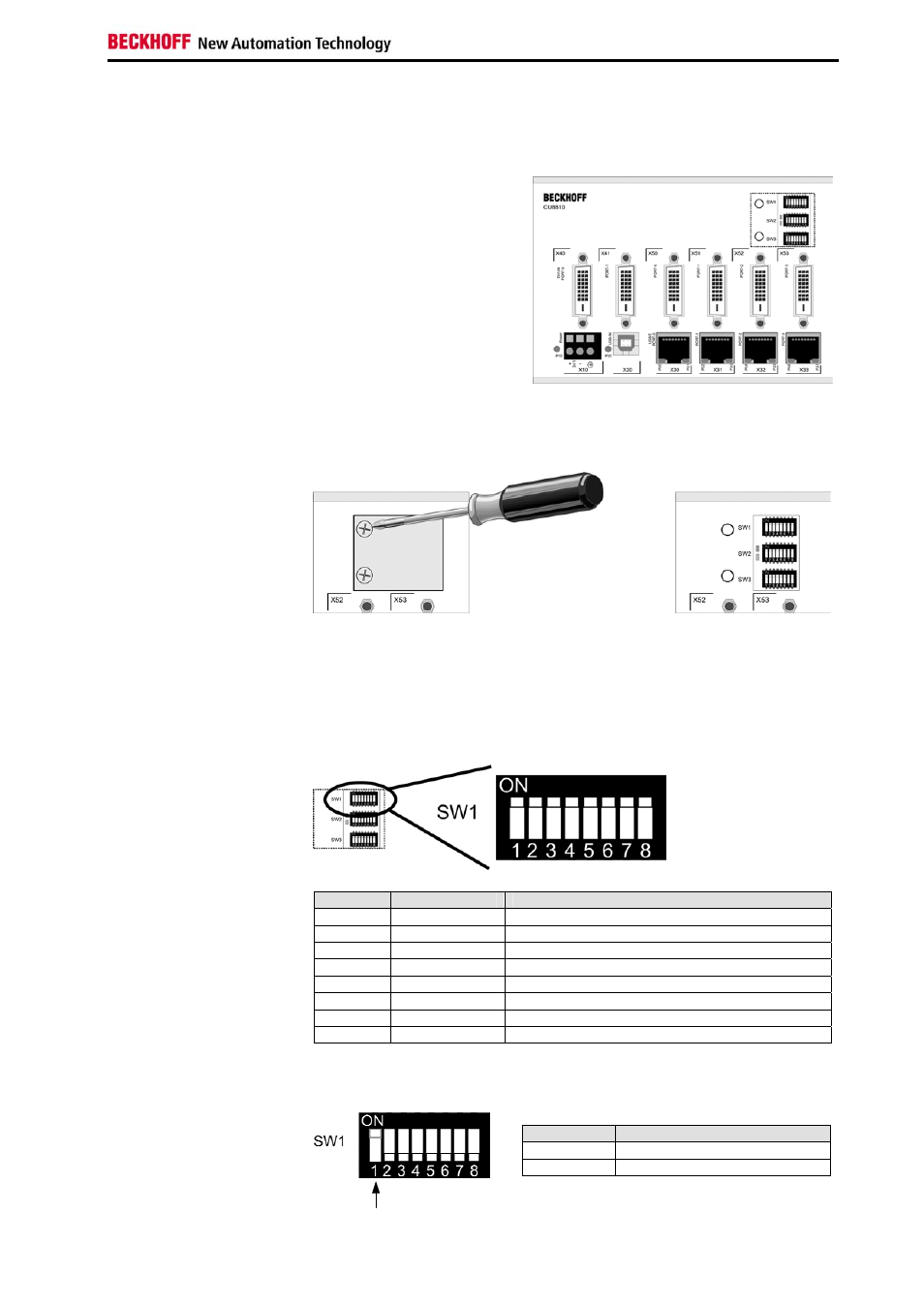
Front view
Front view of the CU8810 with
opened enclosure.
Opening the enclosure
The device is configured by a set of three switches. The switches are
covered by an enclosure on the upper right side on the front. To open the
enclosure you need to remove the two screws, as shown below:
There are three DIP switches and two status LEDs covered by the plate.
The detailed functions are described in the following.
DIP Switch 1 (SW1)
DIP Switch 1 (SW1)
This DIP switch configures the DVI input sources and the DDC signals.
Switch
Name
Function
1
PWRDVI 1
Activate DVI Input Port 0 (X40)
2
PWRDVI 2
Activate DVI Input Port 1 (X41)
3
OUT-LEVEL
Set output level for DVI Output
4 N.C.
Not
used
5
A0_0
Address switch A0 for DVI Input Port 0 (X40)
6
A1_0
Address switch A1 for DVI Input Port 0 (X40)
7
A0_1
Address switch A0 for DVI Input Port 1 (X41)
8
A1_1
Address switch A1 for DVI Input Port 1 (X41)
The first two switches are used to enable/ disable the two DVI Input Ports:
PWRDVI 1
PWRDVI1
Function
on
DVI Input Port 0 is activated
off
DVI Input Port 0 is deactivated
CU8810-0000
9