Characteristics of protection and control elements, Figure 2-1. 87 phase differential element -2 – Basler Electric BE1-CDS240 Quick Start User Manual
Page 4
The concept is the same but the method is different in that you choose each element by enabling it and
use Boolean logic expressions to connect the inputs and outputs. The result is that you have even greater
flexibility in designing your system than you had using discrete devices. An added benefit is that you are
not constrained by the limitations in flexibility inherent in many multifunction relays.
One user programmable, custom logic scheme created by the user may be programmed and saved in
memory. Or, the user may choose from one preprogrammed logic scheme embedded in the relay
firmware or several preprogrammed logic schemes in the BESTCOMS logic library that can be copied to
the relay. Preprogrammed schemes can reduce or eliminate the need for programming by the user.
Preprogrammed logic settings can also be modified after being saved in the relay. This provides a good
starting point for a custom logic scheme. To modify the preprogrammed scheme, it is necessary to enter a
unique name for the new logic before modifying the settings. Naming the new logic distinguishes it from
the preprogrammed logic scheme. In the 16 character preprogrammed logic name, the last 4 characters
refer to revision A, dash (-), and BE (Basler Electric). When customizing a programmed logic scheme, it is
recommended that the user include the revision level of their scheme and change the BE to a 2-digit code
representative of the user's company name. For example, if VA Power were modifying the CDS240-
BATX-A-BE the preprogrammed logic scheme might be CDS240-BATX-B-VP, the B standing for revision
level B, and VP for VA Power.
There are two types of BESTlogic settings: element (function block) logic settings and output logic
settings. These will be described briefly in the following paragraphs. Detailed information on using
BESTlogic to design complete protection and control schemes for the protected circuit can be found in
Section 7, BESTlogic Programmable Logic and Section 8, Application.
Characteristics of Protection and Control Elements
As stated before, each element (function block) is equivalent to a discrete device counterpart. For
example, the transformer differential element in the BE1-CDS240 relay has all of the characteristics of a
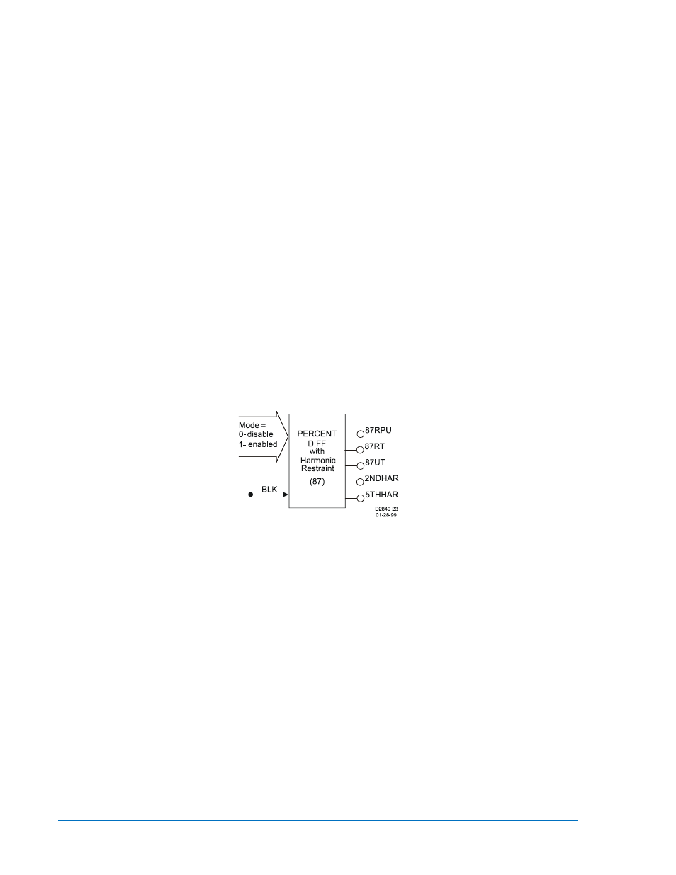
version of the BE1-87T transformer differential relay with similar functionality. Figure 2-1 shows the 87
phase differential element inputs and outputs.
Figure 2-1. 87 Phase Differential Element
Two inputs:
•
Mode (enable/disable 87 operation)
•
BLK (block 87 operation)
Five outputs:
•
87RPU (87 Restrained Pickup)
•
87RT (87 Restrained Trip)
•
87UT (87 Unrestrained Trip)
•
2NDHAR (2
nd
Harmonic Inhibit Status)
•
5THHAR (5
th
Harmonic Inhibit Status)
Five operational settings:
•
Minimum pickup
•
Slope
•
2
nd
Harmonic Inhibit
•
5
th
Harmonic Inhibit
•
Unrestrained Pickup
Of the above characteristics, the five operational settings are not included in the logic settings. They are
included in the protection settings. This is an important distinction. Since changing logic settings is similar
to rewiring a panel, the logic settings are separate and distinct from the operational settings such as
pickups and time delays.
2-2
BE1-CDS240 Quick Start
9365200990 Rev M