Functional description, Introduction, Inputs – Basler Electric BE1-59N User Manual
Page 19: Filters, Overvoltage comparator, Definite time delay (optional), Section 3 • functional description -1, Introduction -1, Inputs -1, Filters -1
SECTION 3 • FUNCTIONAL DESCRIPTION
INTRODUCTION
BE1-59N relay functions are illustrated in Figure 3-1 and described in the following paragraphs.
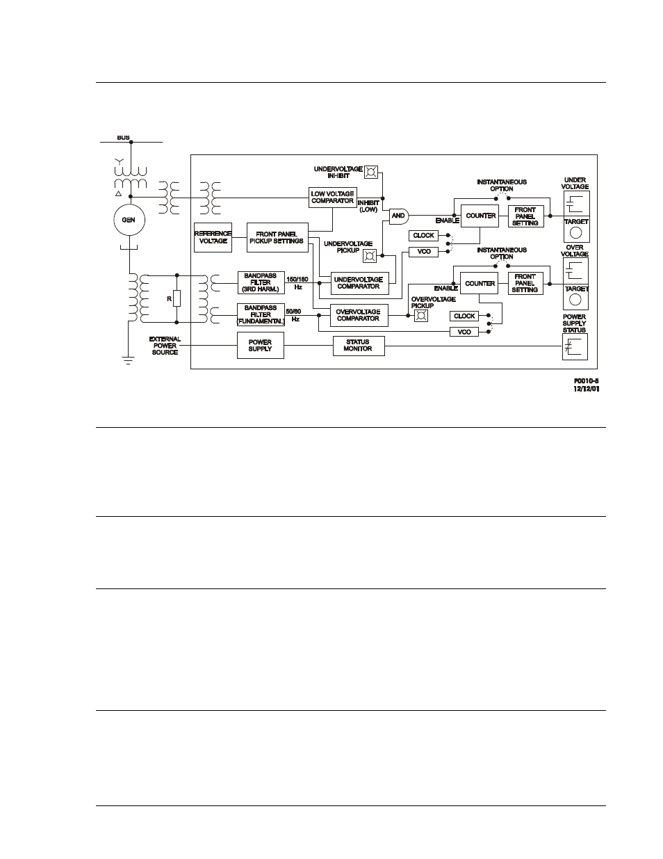
Figure 3-1. Function Block Diagram
INPUTS
The relay senses the level of voltage developed across a resistor connected in the neutral-grounding
transformer secondary. The relay may also be used with ungrounded systems with voltage transformers
connected in a wye/broken delta configuration. These connections are shown in Section 4.
Internal transformers provide further isolation and step down for the relay logic circuits.
FILTERS
A band-pass filter provides peak sensitivity at 50 or 60 Hz for the overvoltage input, with third harmonic
rejection of 40 dB minimum. If an undervoltage element is specified, an additional filter with peak
sensitivity at the third harmonic is included. The filter provides 40 dB rejection of the fundamental.
OVERVOLTAGE COMPARATOR
The overvoltage comparator circuit receives a sensing voltage from the band-pass filter and a reference
voltage from the front panel setting. The comparator determines within five cycles if the fundamental
frequency (50 or 60 hertz) is less than or greater than the reference setting. When the input exceeds the
setting, the resulting comparator output enables the timing circuit if definite or inverse time delay is
specified, and the OVERVOLTAGE PICKUP LED illuminates. If instantaneous timing is used, the
comparator output immediately energizes the overvoltage relay and, if present, the overvoltage auxiliary
relay.
DEFINITE TIME DELAY (OPTIONAL)
An output signal from the comparator circuit enables a counting circuit to be incremented by an internal
clock. When the counting circuit reaches a count, which matches the number entered on the TIME DIAL,
the output relay and auxiliary relay, if present, are energized. However, if the sensed input voltage falls
below the pickup setting before the timer completes its cycle, the timer resets within 2.0 cycles.
9171400990 Rev K
BE1-59N Functional Description
3-1