Target indicators, Target indicators -8, Figure 5-3. 50-b pickup test setup – Basler Electric BE1-50/51B-237 User Manual
Page 46
5-8
BE1-50/51B-237/-238 Testing
9252000899 Rev B
SW3-3 = ON (GE IAC type characteristic curves)
SW3-4 = ON (integrating reset characteristic)
c. Set TIME DIAL to 0.0.
d. Set CURVE to S.
e. Set TIME PICKUP to 3.18.
f. Set INST PICKUP (50-A) to 18.0.
g. Set INST PICKUP (50-B) (accessed at the top side of the assembly) to 20 (0.4 Aac).
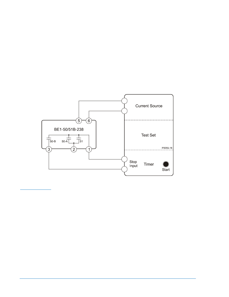
2. Apply and slowly increase current to terminals 5 and 6 until the 50-B output contacts close. The
applied current should be between 0.387 and 0.413 Aac.
3. Decrease the applied current until the 50-B output contacts open.
4. Set INST PICKUP (50-B) to 80 (1.6 Aac).
5. Slowly increase the current applied to terminals 5 and 6 until the 50-B output contacts close. The
applied current should be between 1.563 and 1.637 Aac.
6. Reduce the applied current to zero.
Figure 5-5. 50-B Pickup Test Setup
1. Connect and configure the relay for target indicator testing:
Target Indicators
a. Connect the test setup shown in Figure 5-6.
b. Set circuit board switch SW3 as follows:
SW3-1 = ON for 50 Hz operation or OFF for 60 Hz operation
SW3-2 = OFF (no additional time delay for the 50-A element)
SW3-3 = ON (GE IAC type characteristic curves)
SW3-4 = ON (integrating reset characteristic)
c. Set TIME DIAL to 0.0.
d. Set CURVE to S.
e. Set TIME PICKUP to 0.2.
f. Set INST PICKUP (50-A) to 18.0.
g. Set INST PICKUP (50-B) (accessed at the top side of the assembly) at F0 (3.0 Aac).
2. Apply 0.4 Aac to terminals 5 and 6 to trip the 51 relay output.
3. Slowly increase the voltage source to provide target current and verify that the Time target operates
at the level of current determined by the Target Operating Current Jumpers.