Target indicators, Minimum operating current, Output contacts – Basler Electric BE1-50/51B-237 User Manual
Page 16: Resistive ratings, Inductive ratings, Terminal assignments, Target indicators -6, Output contacts -6, Figure 1-5. harmonic rejection
1-6
BE1-50/51B-237/-238 General Information
9252000899 Rev B
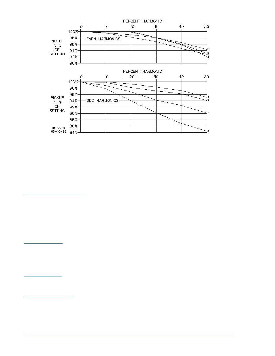
Figure 1-5. Harmonic Rejection
Target Indicators
A gravity-latched, manually-reset, current-operated target indicator is provided for the time-overcurrent
(51) trip output and the instantaneous overcurrent A (50-A) trip output. A target indicator is not provided
for the 50-B trip output. The level of trip circuit current required to operate each target is individually
controlled by a circuit board jumper. See Section 2, Controls and Indicators for jumper locations and
function assignments
Jumper Position—Pins 1 and 2: 0.9 to 2.25 A ∗
Minimum Operating Current
Jumper Position—Pins 2 and 3: 80 mA to 200 mA ∗
*
Minimum operating current values. See Output Contacts for the maximum acceptable levels of trip
circuit currents.
Output Contacts
Output contacts are surge protected and rated as follows.
120/240 Vac ............................... Make 30 amperes for 0.2 seconds, carry 7 amperes for 2 minutes, 3
amperes continuously, and break 5 amperes.
Resistive Ratings
125/250 Vdc ............................... Make 30 amperes for 0.2 seconds, carry 7 amperes for 2 minutes, 3
amperes continuously, and break 0.3 ampere.
120/240 Vac, 125/250 Vdc ........ Make and carry 30 amperes for 0.2 seconds, carry 7 amperes for 2
minutes, 3 amperes continuously, and break 0.3 ampere. (L/R = 0.04).
Inductive Ratings
51 Element ................................. 1, 2
Terminal Assignments
50-A Element ............................. 1, 2
50-B Element ............................. 1, 3