Connections, Connections -3, Figure 4-3. panel drilling diagram, c1 case – Basler Electric BE1-50/51M User Manual
Page 35
9252000990 Rev R
BE1-50/51M Installation
4-3
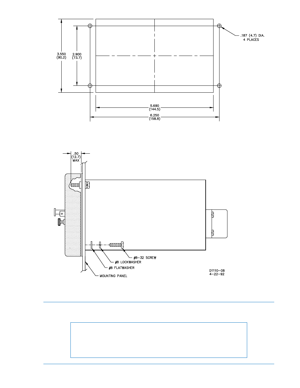
Figure 4-3. Panel Drilling Diagram, C1 Case
Connections
Incorrect wiring may result in damage to the relay. Be sure to check model and part number before
connecting and energizing a particular relay.
NOTE
Be sure that the relay is hard-wired to earth ground with no smaller than 12
AWG copper wire attached to the ground terminal on the rear of the unit case.
When the relay is configured in a system with other devices, it is
recommended to use a separate lead to the ground bus from each unit.
See also other documents in the category Basler Electric Relay:
- BE1-11i RTD Module (672 pages)
- BE1-11m Terminals and Connectors (604 pages)
- BE1-11i RTD Module (554 pages)
- BE1-11 DNP3 Protocol (82 pages)
- BE1-11 IEC 61850 Protocol (100 pages)
- BE1-11 Modbus Protocol (186 pages)
- BE1-851 (364 pages)
- BE1-851E DNP3 Protocol (40 pages)
- BE1-851E Modbus Protocol (70 pages)
- BE1-700 (460 pages)
- BE1-700 Modbus Protocol (92 pages)
- BE1-50 (44 pages)
- BE1-50/51B (76 pages)
- BE1-50/51B-122 (66 pages)
- BE1-50/51B-232 (64 pages)
- BE1-50/51B-231 (60 pages)
- BE1-50/51B-233 (60 pages)
- BE1-50/51B-240 (52 pages)
- BE1-50/51B-241 (52 pages)
- BE1-50/51B-244 (64 pages)
- BE1-50/51B-225 (72 pages)
- BE1-50/51B-228 (68 pages)
- BE1-50/51B-226 (52 pages)
- BE1-50/51B-236 (68 pages)
- BE1-50/51B-239 (76 pages)
- BE1-50/51B-238 (70 pages)
- BE1-51 (100 pages)
- BE1-64F (30 pages)
- BE1-51/27C (112 pages)
- BE1-25 (66 pages)
- BE1-51/27R (114 pages)
- BE1-87G (68 pages)
- BE1-59N (40 pages)
- BE3-25 (2 pages)
- BE3-27T/59T (2 pages)
- BE3-27/59 (2 pages)
- BE3-32 (2 pages)
- BE1-32O/U (82 pages)
- BE3-47 (2 pages)
- BE3-37/51 (2 pages)
- BE3-47N/27 (2 pages)
- BE3-49R-3 Inputs (2 pages)
- BE3-49R-6 Inputs (2 pages)
- BE3-49TL (2 pages)