General, Differences, Section 6 • relay differences -1 – Basler Electric BE1-50/51B User Manual
Page 55: General -1, Differences -1
9252000991 Rev R
BE1-50/51B Relay Differences
6-1
SECTION 6 • RELAY DIFFERENCES
General
This section provides the information necessary to support BE1-50/51B 100 series relays, revision S and
previous. In all unit revisions R and previous SW3 is the same as SW8.
Differences
BE1-50/51B 100 series relay boards revision Q and previous have the locations for controls and
indicators shown in Figure 6-1. BE1-50/51B 100 series relays, unit revisions R and 200 series relays, unit
revisions H and previous have the locations for controls and indicators shown in Figure 6-2. Table 6-1
lists and briefly describes the operator controls of these relays. Reference the callout letters to Figures 6-
1 and 6-2.
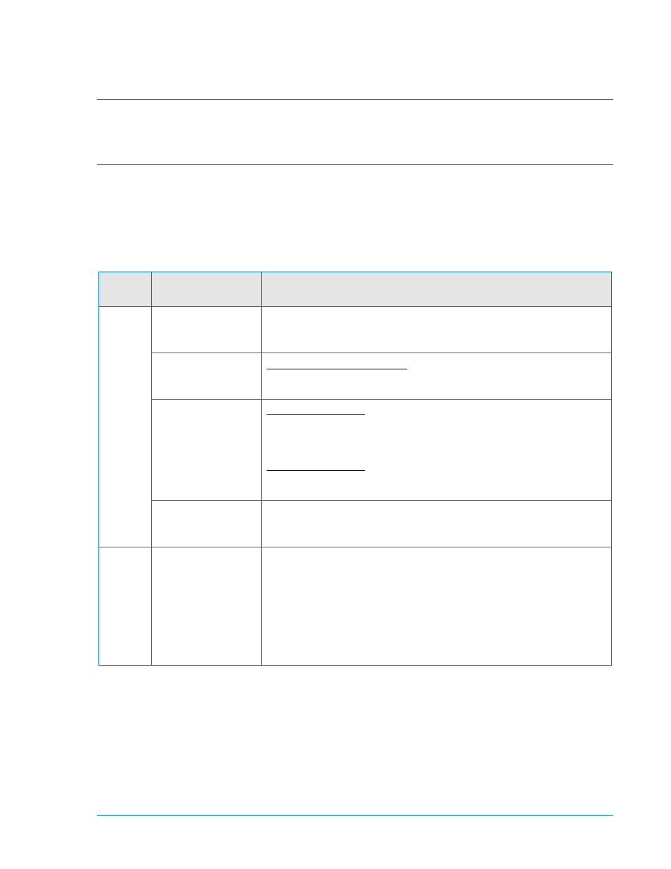
Table 6-1. BE1-50/51B Controls and Indicators for 100 Series Relays Revision Q and Previous
Locator
Control or
Indicator
Function
J
SW8-1
SW8-1 selects the system operating frequency. SW8-1 open (OFF)
selects 60 hertz operation. SW8-1 closed (ON) selects 50 hertz
operation.
SW8-2
In 100 and 200 series relays,
SW8-3
SW8-2 selects additional delay for the
instantaneous element. Switch SW8-2 closed (ON) provides an
additional instantaneous delay of 0.1 seconds.
In 100 series relays, switch SW8-3 closed (ON) provides an
additional instantaneous delay of 0.2 seconds. Closing both switches
SW8-2 and SW8-3 provides an additional instantaneous delay of 0.3
seconds.
In 200 series relays,
SW8-4
SW8-3 open (OFF) selects ABB type curves
(refer to Table 1-3). SW8-3 closed (ON) selects GE IAC type curves
(refer to Table 1-4).
Provides selection of either instantaneous or integrating reset
characteristic. SW8-4 closed (ON) provides integrating reset. SW8-4
open (OFF) provides instantaneous reset.
K
Auxiliary Output
Jumper
Terminations
Configures the auxiliary output contacts to close with either the
instantaneous (50) trip and/or the timed (51) trip.
Jumper E2 to E1A to close the auxiliary contact with the timed (51)
trip. This jumper is yellow and factory installed to close the auxiliary
output contacts with the timed trip.
Jumper E3 to E1B to close the auxiliary contact with the
instantaneous (50) trip. This jumper is blue and factory installed to
close the auxiliary output contacts with the instantaneous trip.