Features descriptions (con.), Paralleling, Voltage margining adjustment – Delta Electronics 4.5V~13.8Vin User Manual
Page 8: Output capacitance
Preliminary DS_NE12S20A_07272007
8
Vin
Vout
Enable
Ground
Ground
Trim
N
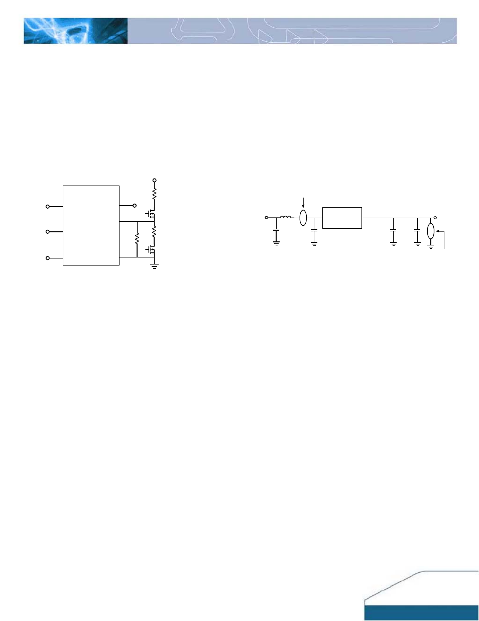
Figure 22: Circuit configuration for output voltage margining
Paralleling
NE20 converters do not have built-in current sharing
(paralleling) ability. Hence, paralleling of multiple NE20
converter is not recommended.
D 6A/10A
Rmargin-down
Rs
Rmargin-up
NE20A
Output voltage margin adjusting can be implemented in
the NE modules by connecting a resistor, R
margin-up
, from
the Trim pin to the Ground for margining
up the output
voltage. Also, the output voltage can be adjusted lower
by connecting a resistor, R
margin-down
, from the Trim pin to
the voltage source Vt. Figure 22 shows the circuit
configuration for output voltage margining adjustment.
Vt
Voltage Margining Adjustment
FEATURES DESCRIPTIONS (CON.)
Output Capacitance
There is internal output capacitor on the NE series
modules. Hence, no external output capacitor is required
for stable operation.
Reflected Ripple Current and Output Ripple and
Noise Measurement
The measurement set-up outlined in Figure 23 has been
used for both input reflected/ terminal ripple current and
output voltage ripple and noise measurements on NE
series converters.
DC-DC Converter
1uF
Ceramic
Tan
10uF
Vin+
Load
Ltest
Cs
Cin
Output voltage ripple noise measurement point
Input reflected current measurement point
Cs=270µF*1, Ltest=2uH, Cin=270µF*1
Figure 23: Input reflected ripple/ capacitor ripple current and
output voltage ripple and noise measurement setup for NE20