ATI Audio DDA416/WC106 User Manual
Page 9
9
DDA‐416/WC106 Manual
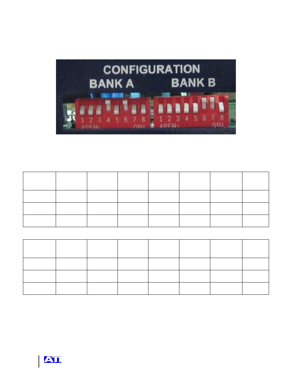
CONFIGURATION DIP Switches
Provides routing and other selections for signal flow in the unit. See the DIP Switch Routing Table
for settings:
The switches are labeled left to right BANK A switch “1” is “DIP Switch 1 in the following tables. In
this view Outputs 1-4 are connected to input 1. OUTPUT 5 to 8 are connected to Word Clock
generated by the WORD CLOCK INPUT.
SOURCE SELECTION FOR AES/EBU OUTPUTS 1, 2, 3 & 4
Selected
Source →
AES
INPUT 1
AES
INPUT 2
AES
INPUT 3
AES
INPUT 4
AES
SYNC
INPUT
WORD
CLOCK
INPUT
AES 1
FRAME
CLOCK
DIP
Switch 1
Down Up Down Up Down Up Up
DIP
Switch 2
Down Down Up
Up Down Down Up
DIP
Switch 3
Down Down Down Down Up
Up Up
SOURCE SELECTION FOR AES/EBU OUTPUTS 5, 6, 7 & 8
Selected
Source →
AES
INPUT 1
AES
INPUT 2
AES
INPUT 3
AES
INPUT 4
AES
SYNC
INPUT
WORD
CLOCK
INPUT
AES 1
FRAME
CLOCK
DIP
Switch 4
Down Up Down Up Down Up Up
DIP
Switch 5
Down Down Up
Up Down Down Up
DIP
Switch 6
Down Down Down Down Up
Up Up