Aplex Technology ACS-2170 User Manual
Page 25
ACS-2170 User Manual
24
26. LED1,LED2 (option) :
LED1: LED STATUS. Green LED for Motherboard Standby Power Good status.
LED2: LED STATUS. Green LED for Touch Power status.
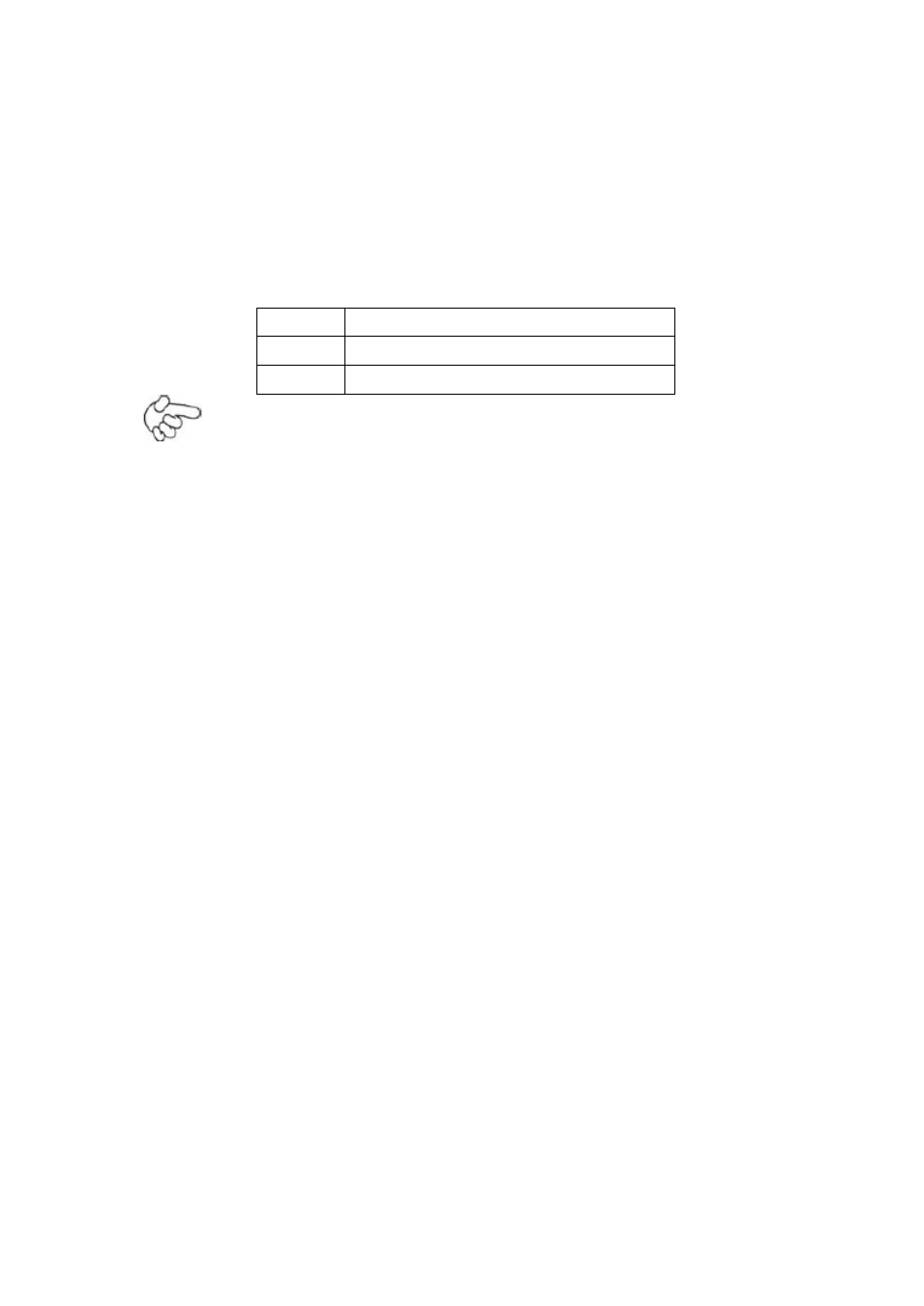
27. SATA_P:
(2.5mm Pitch 1x2 box Pin Header), One onboard 5V output connector are
reserved to provide power for SATA devices.
Pin#
Signal Name
1
+DC5V
2
Ground
Note:
Output current of the connector must not be above 1A.
28. SATA2:
(SATA 7Pin), SATA Connectors, one SATA connector are provided, with transfer
speed up to 3.0Gb/s.
29. SATA1:
(SATA 7Pin+15Pin), SATA Connectors, one SATA connector are provided, with
transfer speed up to 3.0Gb/s.
30. SD1:
(SD card slot), Secure Digital Memory Card socket.
31. MPCIE1:
(Socket 52Pin), mini PCIe socket, it is located at the top, it supports mini PCIe
devices with USB2.0 and LPC and SMBUS and PCIe signal. MPCIe card size is
30x50.95mm.
32. H1/H2:
MPCIE1 SCREW HOLES, H1and H2 for mini PCIE card (30mmx50.95mm)
assemble.
33. F_AUDIO1:
(2.0mm Pitch 2X6 Pin Header), Front Audio, An onboard Realtek ALC662-VD
codec is used to provide high-quality audio I/O ports. Line Out can be connected
to a headphone or amplifier. Line In is used for the connection of external audio