Aplex Technology ACS-2645 User Manual
Page 33
ACS-2645 User Manual
33
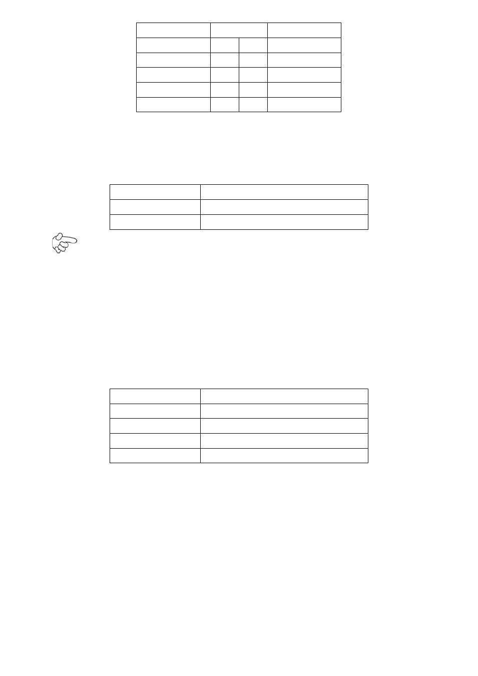
Function
Pin#
Function
+5V
1
2
Ground
GPIO_IN1
3
4
GPIO_IN2
GPIO_IN3
5
6
GPIO_IN4
GPIO_OUT1
7
8
GPIO_OUT2
GPIO_OUT3
9
10
GPIO_OUT4
42. SATA_P1/SATA_P2:
(2.5mm Pitch 1x2 Pin wafer connector), Two onboard 5V output connectors are reserved to provide
power for SATA devices.
Pin#
Signal Name
1
+DC5V
2
Ground
Note:
Output current of the connector must not be above 1A.
43. SATA1/SATA2:
(SATA 7P), SATA Connectors, Two SATA connectors are provided, with transfer speed up to
3.0Gb/s.
44. CON1(option):
(2.0mm Pitch 1x4 Pin wafer connector),Smbus Signal connector.
Pin#
Signal Name
1
SMB_CLK_MAIN_IO
2
3.3V
3
Ground
4
SMB_DATA_MAIN_IO
45. SIM1(option):
(SIM Socket 7Pin), Support SIM Card devices.
46. HS1/HS2/HS3/HS4(CPU SCREW HOLES):
CPU FAN SCREW HOLES, Four screw holes for fixed CPU Cooler assemble.
47. H5/H6:
MPCIE1 SCREW HOLES, H5 for mini PCIE card (30mmx30mm) assemble. H6 for mini PCIE card
(30mmx50.95mm) assemble.