4 jumpers setting and connectors – Aplex Technology ACS-2645 User Manual
Page 19
ACS-2645 User Manual
19
2.4 Jumpers Setting and Connectors
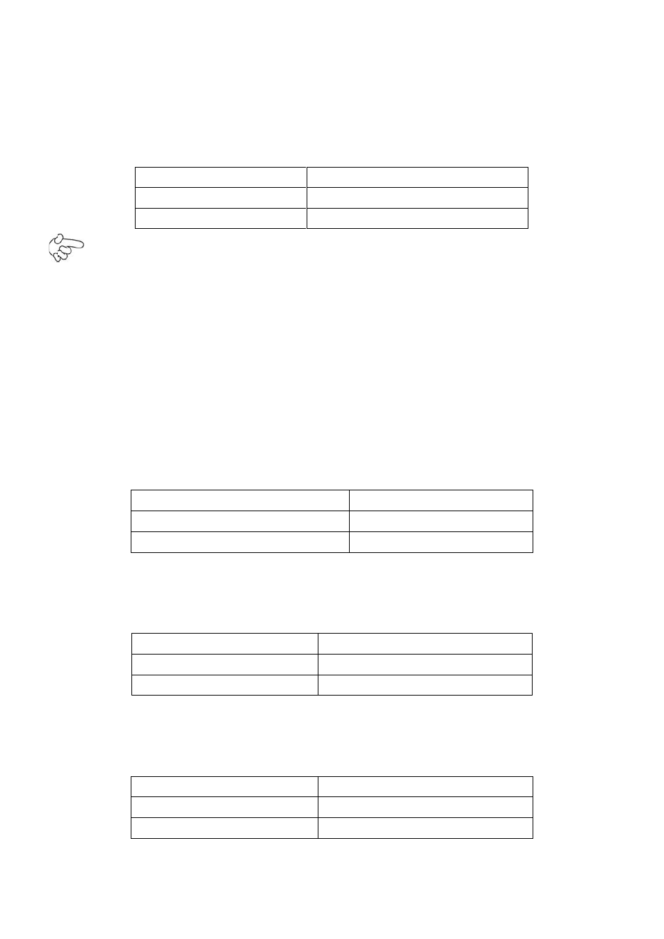
1. JP1:
(2.0mm Pitch 1X3 Pin Header)CMOS clear jumper, CMOS clear operation will permanently reset old
BIOS settings to factory defaults.
JP1
CMOS
Close 1-2
NORMAL (Default)
Close 2-3
Clear CMOS
Procedures of CMOS clear:
a) Turn off the system and unplug the power cord from the power outlet.
b) To clear the CMOS settings, use the jumper cap to close pins2 and 3 for about 3
seconds then reinstall the jumper clip back to pins open.
c) Power on the system again.
d) When entering the POST screen, press the key to enter CMOS Setup
Utility to load optimal defaults.
e) After the above operations, save changes and exit BIOS Setup.
2. BAT1:
(1.25mm Pitch 1X2 Pin wafer connector) 3.0V Li battery is embedded to provide power for CMOS.
Pin#
Signal Name
Pin1
VBAT
PIN2
Ground
3. PS_SEL1(option):
(2.0mm Pitch 1X3 Pin Header),DC in Power and ATX 12V IN Power jumper setting.
PS_SEL1
Mode
Close 1-2
DC IN Power (Default)
Close 2-3
ATX 12V_IN (ATX Power)
4. PS_ON:
(2.0mm Pitch 1X3 Pin Header),ATX Power and Auto Power on jumper setting.
JP2
Mode (DC_IN)
Close 1-2
Auto Power on (Default)
Close 2-3 or Open 1-2
ATX Power