Aplex Technology ACS-2645 User Manual
Page 27
ACS-2645 User Manual
27
JP3 Pin#
Function
Close 1-2
COM2 RI (Ring Indicator) (default)
Close 3-4
COM2 Pin9=+5V (option)
Close 5-6
COM2 Pin9=+12V (option)
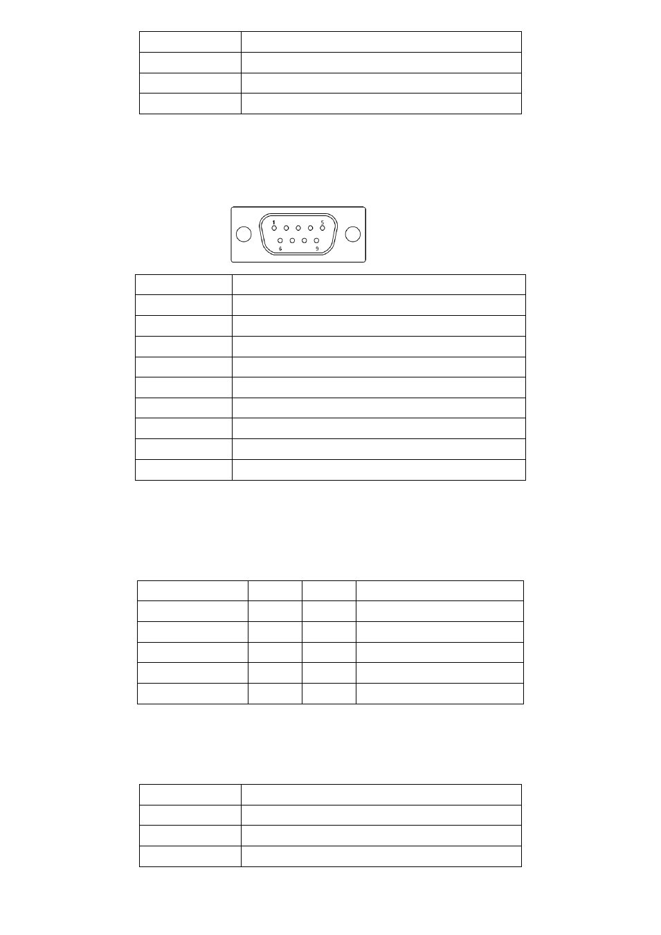
24. COM2:
(Type DB9),
Rear serial port, standard DB9 Male serial port is provided to make a direct
connection to serial devices.
Pin#
Signal Name
1
DCD# (Data Carrier Detect)
2
RXD (Received Data)
3
TXD (Transmit Data)
4
DTR (Data Terminal Ready)
5
Ground
6
DSR (Data Set Ready)
7
RTS (Request To Send)
8
CTS (Clear To Send)
9
RI/5V/12V (JP3 select Setting)
25. COM5
:
(2.0mm Pitch 2X5 Pin Header),COM5 Port, standard RS232 ports are provided. They can be used
directly via COM cable connection.
Signal Name
Pin#
Pin#
Signal Name
DCD
1
2
RXD
TXD
3
4
DTR
Ground
5
6
DSR
RTS
7
8
CTS
RI
9
10
NC
26. JP4:
(2.0mm Pitch 2x3 Pin Header) COM6 setting jumper, pin 1~6 are used to select signal out of pin 9
of COM6 port.
JP4 Pin#
Function
Close 1-2
COM6 RI (Ring Indicator) (default)
Close 3-4
COM6 Pin9=+5V (option)
Close 5-6
COM6 Pin9=+12V (option)