Aplex Technology APC-3519 User Manual
Page 28
28
Close 1-2
COM6 Pin9 RI (Ring Indicator) (default)
Close 3-4
COM6 Pin9=+5V
(option)
Close 5-6
COM6 Pin9=+12V
(option)
25. COM6
:
(2.0mm Pitch 2x5 Pin Header), COM6 Port, standard RS232 ports are provided. They
can be used directly via COM cable connection. COM6 port is controlled by pins No.1~6
of JP3,select output Signal 5V or 12v, For details, please refer to description of JP3.
Signal Name
Pin#
Pin#
Signal Name
DCD
1
2
RXD
TXD
3
4
DTR
Ground
5
6
DSR
RTS
7
8
CTS
JP3 select Setting
(RI/5V/12V)
9
10
NC
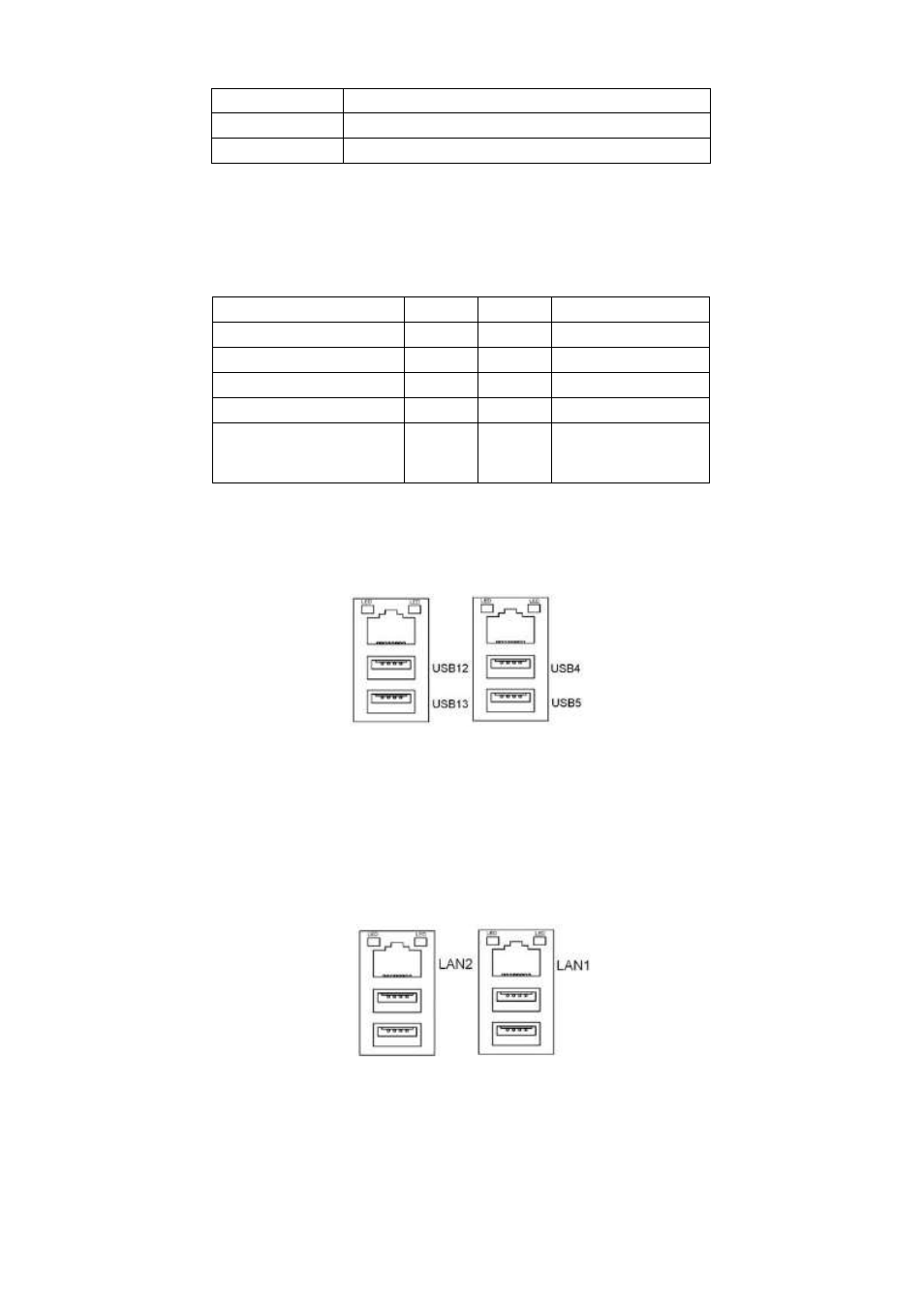
26. USB_LAN1/USB_LAN2
:
USB4/USB5/USB12/USB13 : (Double stack USB type A), Rear USB
connector, it
provides up to 4 USB2.0 ports, speed up to 480Mb/s.
Each USB Type A Receptacle (2 Ports) Current limited value is 1.5A.
If the external USB device current exceeds 1.5A, please separate connectors into
different Receptacle.
LAN1/LAN2: (RJ45 Connector), Rear LAN port, Two standard 10/100/1000M RJ-45
Ethernet ports are provided. Used Intel 82574L chipset, LINK LED (green) and ACTIVE
LED (yellow) respectively located at the left-hand and right-hand side of the Ethernet
port indicate the activity and transmission state of LAN.
27. JACK1
:
(Diameter 3.5mm Double stack Jack), HD Audio port, An onboard Realtek ALC662 codec
is used to provide high quality audio I/O ports. Line Out can be connected to a headphone