Aplex Technology APC-3519 User Manual
Page 23
23
Pin1
DC+12V
Pin2
Ground
Pin3
Ground
Pin4
DC+5V
9. U1:
(Socket G2), installing the 2nd GEN intel Core i3/i5/i7CPU Socket.
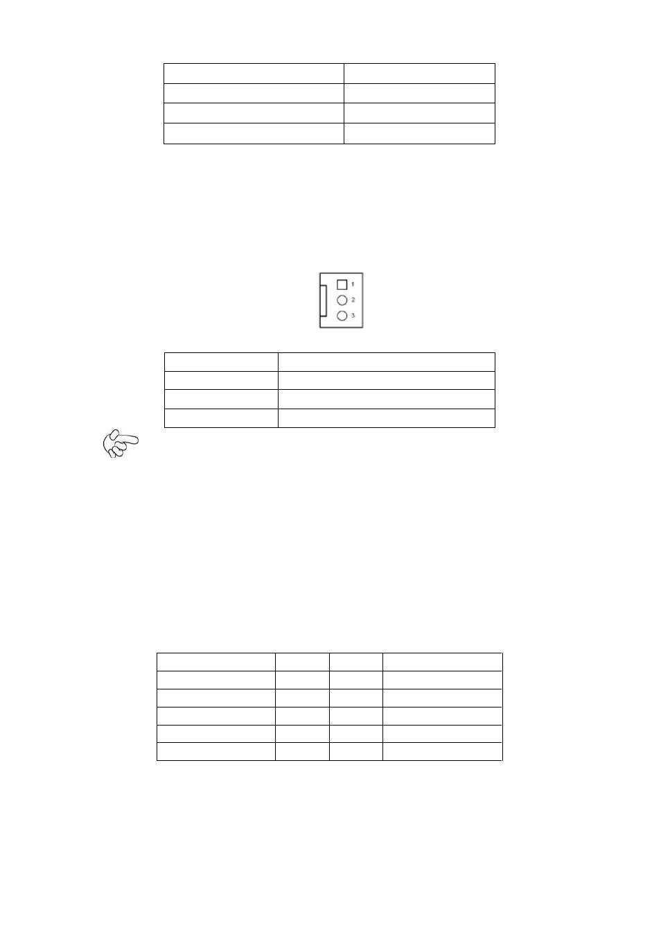
10. CPU_FAN1/SYS_FAN1:
(2.54mm Pitch 1x3 Pin Header),Fan connector, cooling fans can be connected directly for
use. You may set the rotation condition of cooling fan in menu of BIOS CMOS Setup.
Pin#
Signal Name
1
Ground
2
VCC
3
Rotation detection
Note:
Output power of cooling fan must be limited under 5W.
11. A-DDR3/B-DDR3:
(SO-DIMM 204Pin socket), DDRIII memory socket, the socket is located at the top of the
board and supports 204Pin 1.5V DDRIII 1066/1333/1600MHz FSB SO-DIMM memory
module up to 16GB.
12. VGA1:
(CRT 2.0mm Pitch 2X5 Pin Header), Video Graphic Array Port, Provide 2x5Pin cable to
VGA Port.
Signal Name
Pin#
Pin#
Signal Name
CRT_RED
1
2
Ground
CRT_GREEN
3
4
Ground
CRT_BLUE
5
6
Ground
CRT_H_SYNC
7
8
CRT_DDCDATA
CRT_V_SYNC
9
10
CRT_DDCCLK
13. INVT1:
(2.0mm Pitch 1x6 box Pin Header), Backlight control connector for LVDS1.