Aplex Technology APC-3519 User Manual
Page 24
24
Signal Name
Pin#
Pin#
Signal Name
VDD5
2
1
VDD5
Ground
4
3
Ground
VDD33
6
5
VDD33
LB_D0_N
8
7
LA_D0_N
LB_D0_P
10
9
LA_D0_P
Ground
12
11
Ground
LB_D1_N
14
13
LA_D1_N
LB_D1_P
16
15
LA_D1_P
Ground
18
17
Ground
LB_D2_N
20
19
LA_D2_N
LB_D2_P
22
21
LA_D2_P
Ground
24
23
Ground
LB_CLK_N
26
25
LA_CLK_N
LB_CLK_P
28
27
LA_CLK_P
Ground
30
29
Ground
VLVDS_DDC_DATA
32
31
LVDS_DOC_CLK
Ground
34
33
Ground
LB_D3_N
36
35
LA_D3_N
LB_D3_P
38
37
LA_D3_P
NC
40
39
NC
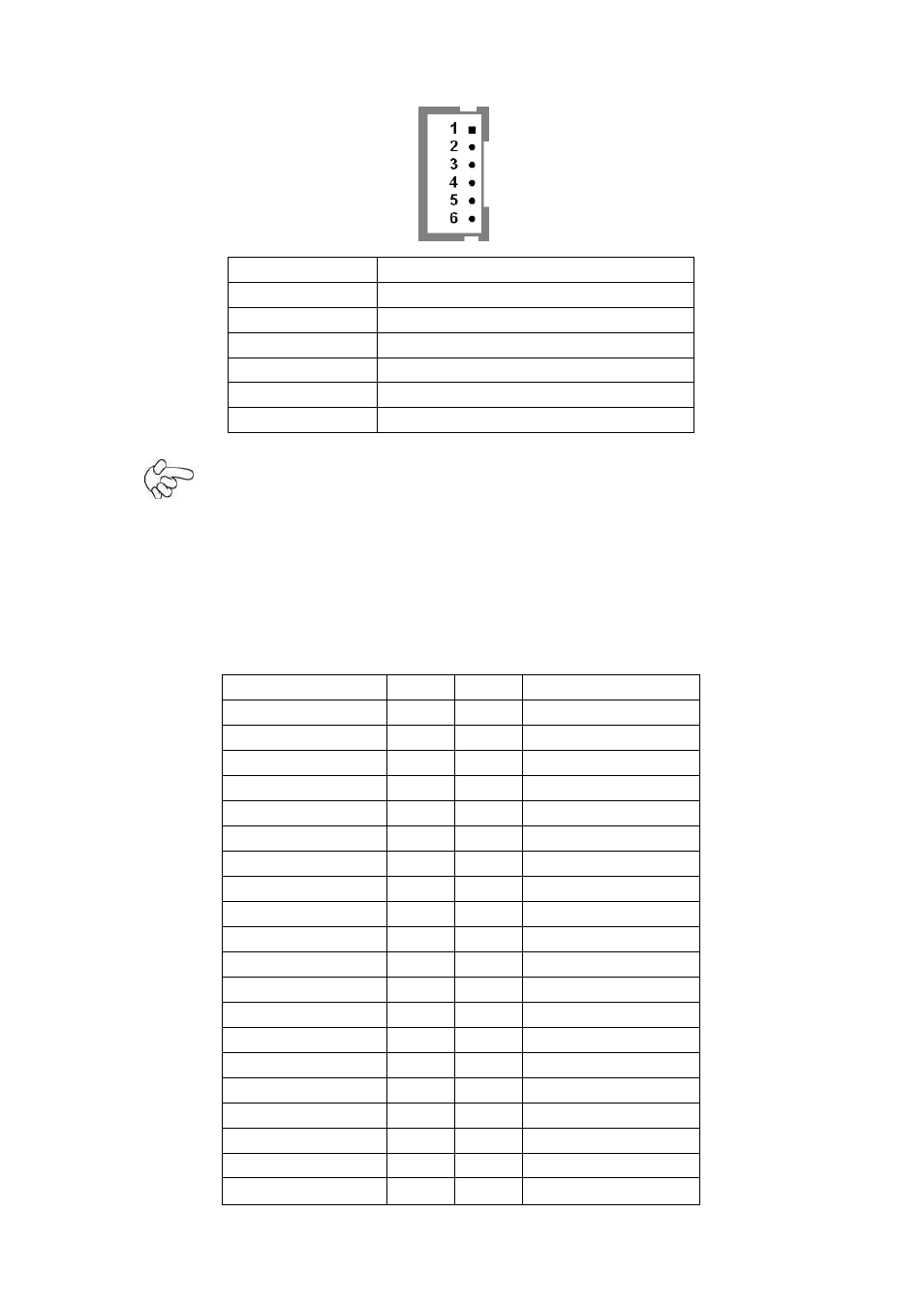
Pin#
Signal Name
1
+DC12V
2
+DC12V
3
Ground
4
Ground
5
BKLT_EN
6
BKLT_CTRL
Note:
Pin6 is backlight control signal, support DC or PWM mode, mode select at BIOS CMOS
menu.
14. LVDS1:
(1.25mm Pitch 2x20 Connector), For 18/24-bit LVDS output connector, Fully supported
by Intel QM67 chipset, the interface features dual channel 18/24-bit output.
L