4 compressor post eq block diagram, 5 512c preamp block diagram – API Audio The Channel Strip User Manual
Page 7
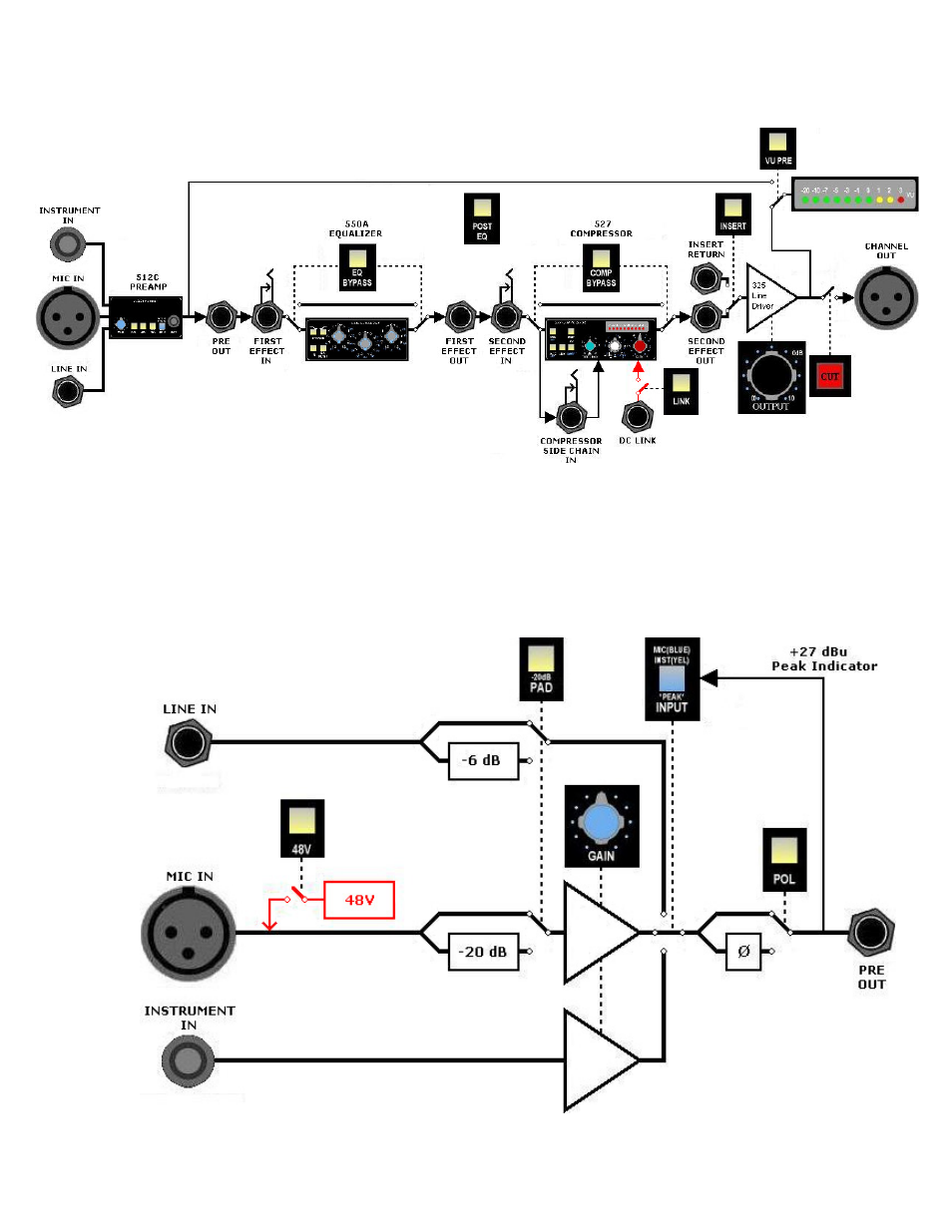
2.4 Compressor Post EQ Block Diagram
The block diagram below illustrates The Channel Strip signal flow with the POST EQ switch engaged. No
other switches are engaged except the CUT button.
NOTE: The order of the First and Second Effect jacks on the rear panel does not change with the
compressor when the POST EQ switch is engaged.
2.5 512C Preamp Block Diagram
The block diagram below illustrates signal flow through the 512C Preamp section of The Channel Strip
with no switches engaged.
6