4 line input, 4 polarity inverter, 5 level indication – API Audio The Channel Strip User Manual
Page 11: 1 vu meter, 2 peak indicator, 6 preamp output
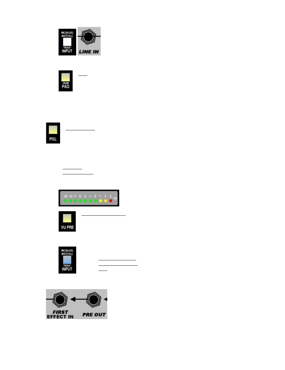
3.3.4 Line
Input
Select the line input by pressing the INPUT switch until it is not illuminated.
The ¼” LINE IN jack on the rear panel will be the active input.
•
+4dBu live level input
•
Balanced, low-impedance input (¼” tip-ring-sleeve)
•
-6dB pad
•
Unity gain
•
INPUT switch is not illuminated when engaged (white)
•
Red peak indication when output exceeds +27dBu
PAD: Inserts a -6dB attenuator after the line input
•
Illuminates when engaged
3.4 Polarity Inverter
A polarity inverter (sometimes referred to as a “phase reverse”) is available at the output of the 512C
Preamp.
POL (Polarity): Inverts the polarity of the signal at the output of the preamp
•
Illuminates when engaged
3.5 Level Indication
The output level of the 512C Preamp can be monitored in two (2) ways:
•
VU Meter: The VU meter in the output section can display the preamp output level
•
Peak Indicator: The INPUT switch doubles as a peak indicator
3.5.1 VU Meter
The output of the 512C Preamp will be displayed on the VU meter
when the VU PRE switch is engaged
VU PRE (VU Preamp): Routes the output of the 512C Preamp to the VU meter input
•
Illuminates when engaged
3.5.2 Peak Indicator
3.6
Preamp Output
The INPUT switch also serves as a peak indicator when the output of the 512C Preamp
exceeds +27dBu. The INPUT switch will change color as follows to indicate peak levels:
•
MIC (Microphone): Changes from blue to violet
•
INST (Instrument): Changes from yellow to orange
•
Line: Changes from white to red
The output of the 512C Preamp is available at the PRE OUT jack on the
rear panel. That jack is “half-normalled” to the FIRST EFFECT IN jack on
the rear panel.
•
Balanced, low-impedance, +4dBu line level output
•
¼” tip-ring-sleeve jack
•
Plugging into the PRE OUT jack does not break the connection to
the FIRST EFFECT IN jack.
10