0 signal flow and block diagrams, 1 default signal flow, 2 alternate routing – API Audio The Channel Strip User Manual
Page 5: 1 compressor post eq, 2 compressor bypass
2.0 Signal Flow and Block Diagrams
2.1 Default Signal Flow
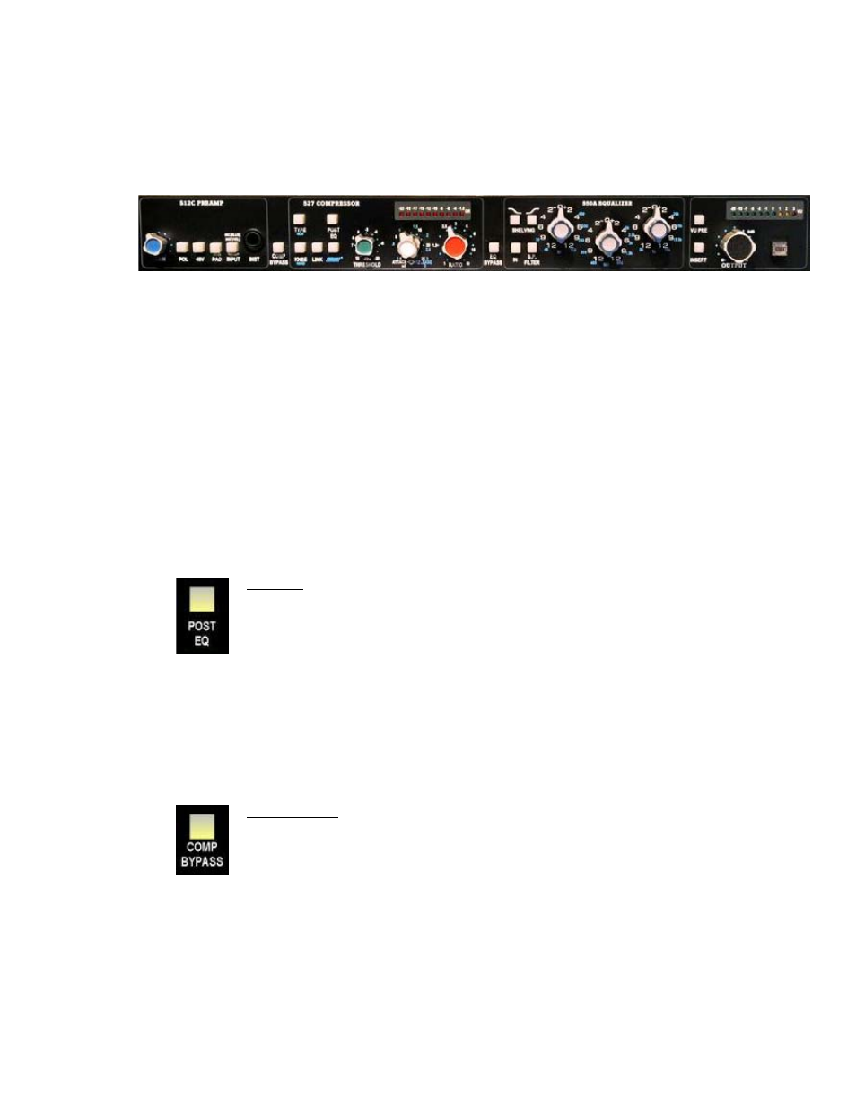
With no routing switches engaged, the default signal flow through The Channel Strip is illustrated by the
left-to-right order of the unit’s front panel:
512C Preamp ----------> 527 Compressor --------------> 550A Equalizer---> Insert --> Output
2.2 Alternate Routing
The default signal flow can be modified in four (4) ways:
•
The 527 Compressor can be moved after the 550A Equalizer
•
The 527 Compressor can be hard bypassed
•
The 550A Equalizer can be hard bypassed
•
Insert Return can be engaged
Since each of these routing functions are independent of each other, multiple signal flow configurations
are possible. Combined with the open interfacing available on the rear panel, comprehensive and
flexible routing possibilities are available to meet most production needs.
2.2.1 Compressor Post EQ
Engaging the POST EQ switch will move the 527 Compressor to after the 550A Equalizer. When
the POST EQ switch is engaged, the signal flow will be as follows:
512C Preamp -----> 550A Equalizer -----> 527 Compressor -----> Insert -----> Output
POST EQ: Moves the 527 Compressor to after the 550A Equalizer
•
527 will use Second Effect rear panel interface jacks
•
Illuminates when engaged
2.2.2 Compressor Bypass
Engaging the COMP BYPASS switch will completely remove the 527 Compressor from the signal
path using a relay-based hard bypass. The 527 Compressor will be bypassed regardless of its
assigned position in the signal flow. When the COMP BYPASS switch is engaged, the signal flow
will be as follows:
512C Preamp -----> 550A Equalizer -----> Insert -----> Output
COMP BYPASS: Removes the 527 Compressor from the signal flow
•
527 will not be accessible via rear panel interface jacks
•
Illuminates when engaged
4