1 intfc setup switch, Isolated remote analog interface operation – AMETEK DLM 600W Series Programming Manual User Manual
Page 13
SECTION 2
ISOLATED REMOTE ANALOG
INTERFACE OPERATION
2.1 INTFC SETUP Switch
The INTFC SETUP (Interface Setup) switch is accessible from the rear panel of the unit. It
provides user selectability of the programming/monitoring ranges and signal types, as well as
configuring the power supply for operation under remote control. Setting a switch to the UP
position enables a function. The factory default settings are all switch positions OFF (down).
See Figure 2–1 for a rear panel view of low-voltage models DLM5–75M51A, DLM 8–75M51A,
DLM 20–30M51A, DLM 40–15M51A, and DLM 60–10M51A. Refer to Figure 2–2 for a rear
panel view of high-voltage models DLM 80–7.5M51A, DLM 150–4M51A, and DLM 300–2M51A.
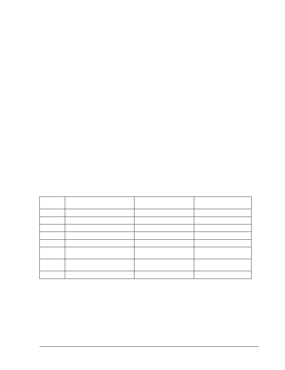
Switch
Position
Function
OFF (Down) Position
ON (Up) Position
1
V, 10V or 4-20mA Select
0-5VDC
0-10VDC or 4-20mA
2
I, 10V or 4-20mA Select
0-5VDC
0-10VDC or 4-20mA
3
OVP, 10V Select
0-5VDC
0-10VDC
4
VMON, 10V Select
0-5VDC or 4-20mA
0-10VDC
5
IMON, 10V Select
0-5VDC or 4-20mA
0-10VDC
6
EXT-OFF, Active-Low
Select
Active-High Logic Level Active-Low Logic Level
7 LCK-OUT
Enable Front Panel
Controls
Lockout Front Panel
8 Not
Used
—
—
Table 2–1. INTFC SETUP Switch
M51A Option
2-1