AMETEK ASD Series Quick Start User Manual
Page 5
5
ASD 30kW Quick Reference Guide
– rev X1
© 2011 AMETEK Programmable Power, Inc. All rights reserved.
www.programmablepower.com
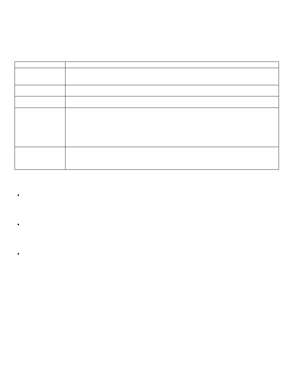
External Switches
The eight position DIP switch labeled DGTL SETUP is used for power supply configuration. The following table lists each
position and its function
Switch number
Description
1
DOWN (on) = 0
– 10 VDC monitor signals and analog programming references
UP (off) = 4
– 20 mADC monitor signals and analog programming references. If the input current
is lower than 2 mA, the unit will generate a fault.
2
DOWN (on) = remote voltage sense disabled.
UP (off) = remote voltage sense enabled.
3
DOWN (on) = master enabled (sets the master as active).
UP (off) = master disabled (the modules in the chassis will operate with an external master).
4 to 7
Unit address or expected number of modules, depending on switch 8.
Use these switches to define a binary number from 0 to 15 (1111 in binary), switch 4 is the least
significant bit and switch 7 the most significant.
DOWN (on) is a binary ZERO
UP (off) is a binary ONE
The unit address or expected number of modules will be the binary value plus one (giving a
range of 1 to 16).
8
DOWN (on) = switches 4-7 are used to set the unit address, necessary for the digital interface.
UP (off) = switches 4-7 are used to indicate the power supply how many modules it should
expect to discover. For more details please see the description of the expected number of
modules feature.
Expected number of modules feature
When this feature is enabled (switch #8 UP or from the digital interface) the master will expect to discover a
predefined number of modules. If the number of modules is lower than the expected, the unit will generate a fault
indicating that there may be a problem with one or more modules. This feature also fixes the analog interface scale
based on the expected number of modules, making it independent from the actual number of modules that were
discovered.
For example, if in a 60V unit the predefined number of modules is 6 (switches 6 and 4 UP), the total available output
current with 6 modules would be 1000A, so the analog interface full scale (10V or 20mA) would be 1000A regardless
of the actual number of connected modules. If there are 3 discovered modules because the 2nd chassis was not
powered-up, the analog interface scale will be fixed based on the EXPECTED number of modules, and the master will
generate a fault because there were too few discovered modules.
If this feature is not used, the actual number of modules discovered by the master will define the analog interface
scale. For example, three 60 V modules give 500 A full scale, or six 60 V modules give 1000 A.