AMETEK ASD Series Quick Start User Manual
Page 2
2
ASD 30kW Quick Reference Guide
– rev X1
© 2011 AMETEK Programmable Power, Inc. All rights reserved.
www.programmablepower.com
If a “MODULE” LED is red but the “AC INPUT” is green, that means that there is a warning in the module but it is still
active, if the “AC INPUT” also turns red, it means that a module had a fault.
Isolated Analog Interface
The power supply output current, voltage, and power can be programmed and monitored via the 25 pin
“ANALOG
INTERFACE” connector. The analog inputs and outputs can be configured (from the external switch and/or the digital
interface) to read or generate voltage or current signals. Full scale reference (0 to 10 VDC or 4 to 20mA) signal
represents full scale output current/voltage/power.
The analog and digital signals available in this interface are galvanically isolated from the power supply outputs. This
interface is not designed to withstand a high voltage potential with respect to earth ground.
If operating with current signals (4-20mA), the unit will generate a fault if any of the inputs has less than 2mA. By
default this fault will shut-down the unit, but this behavior can be changed from the digital interface.
If the unit is enabled via the analog interface, it will respond only to the analog setpoints and not to the digital interface
setpoints.
The full scale of the analog interface depends on the number of modules that are connected to the unit, both internal
and external modules. See Expected Number of Modules section for more details.
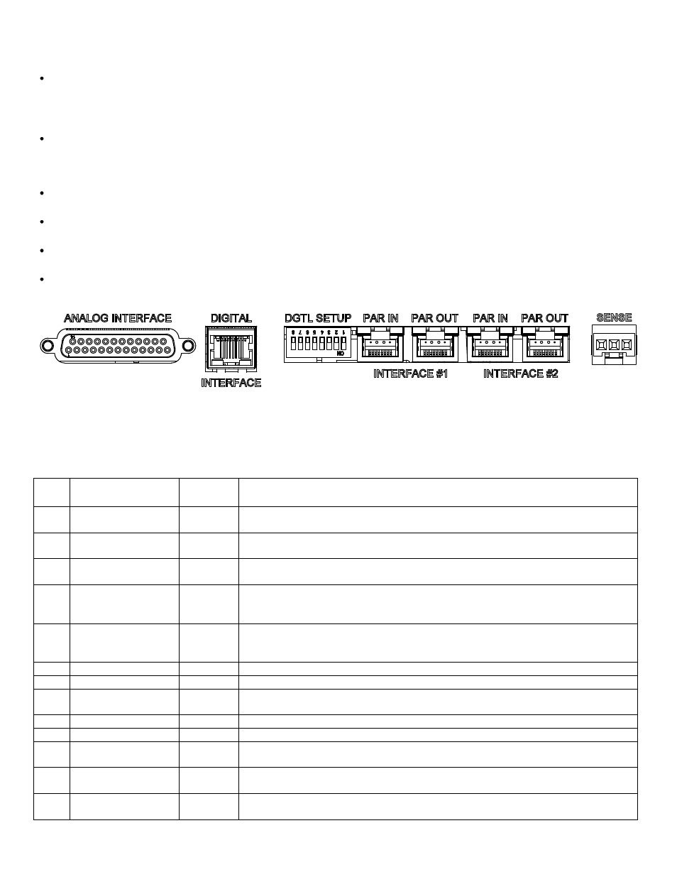
Figure 2: External interface on the rear panel.
The following two tables describe the available input and output signals at the DB25 connectors for standard ASD
units and the SG compatible interface.
Table 1: Analog interface signals. Standard ASD pin-out.
PIN
#
PIN NAME
IN/OUT
DESCRIPTION
1
I_MON
OUT
a 0-10 VDC monitor signal (or 4-20 mADC) that indicates zero to full scale
output current
2
V_MON
OUT
a 0-10 VDC monitor signal (or 4-20 mADC) that indicates zero to full scale
output voltage
3
P_MON
OUT
a 0-10 VDC monitor signal (or 4-20 mADC) that indicates zero to full scale
output power
4
V_MODE_DOUT
OUT (*)
LO indicates the unit is not in voltage mode, HI indicates the unit is in voltage
mode if I_MODE is low. If both I_MODE and V_MODE are HI, it means power
mode.
5
I_MODE_DOUT
OUT (*)
LO indicates the unit is not in current mode, HI indicates the unit is in current
mode if V_MODE is low. If both I_MODE and V_MODE are HI, it means power
mode.
6
STATUS_DOUT
OUT (*)
LO indicates output disabled, HI indicates the output is enabled.
7
FAULT_DOUT
OUT (*)
LO indicates normal operation, HI indicates a fault.
8
DOUT_REF_IN
IN
Used to define the output high level of the digital outputs. If not connected, the
output high is 12V. If connected to 24Vdc, the output high is 24V.
9
GND
common
Same as pin 16
10
+24Vdc
OUT
+24VDC, same as pin 17
11
I_PROG_AIN
IN
a 0-10 VDC analog input signal (or 4-20 mADC) that programs zero to full
scale output current
12
V_PROG_AIN
IN
a 0-10 VDC analog input signal (or 4-20 mADC) that programs zero to full
scale output voltage
13
P_PROG_AIN
IN
a 0-10 VDC analog input signal (or 4-20 mADC) that programs zero to full
scale output power