Keypad circuit, Isp connector – Zilog S3F80QB User Manual
Page 20
UM026703-1014
Keypad Circuit
S3F80QB Development Kit
User Manual
17
Keypad Circuit
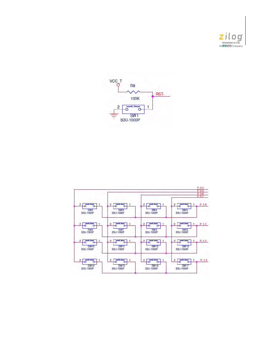
The keypad circuit features 16 switches connected to eight pins on the MCU. These pins
are configured as outputs for P1.3–P1.0, and are configured as inputs with pull-ups
enabled for P0.7–P0.4. The keypad circuit is shown in Figure 18.
ISP Connector
The ISP connector (J6) provides an interface between the S3 Flash ISP tool and the
S3F80QB device. See Figure 19 for an illustration of the ISP connector.
Figure 17. The Reset Circuit
Figure 18. The Keypad Circuit
See also other documents in the category Zilog Sensors:
- S3F94C8 (11 pages)
- S3F8S19 (38 pages)
- Z51F6412 (54 pages)
- Z51F6412 (55 pages)
- Z51F6412 (96 pages)
- EZ80F93 (11 pages)
- Z16F6411 (20 pages)
- Z16F6411 (216 pages)
- EZ80F93 (13 pages)
- ZMOT0BSB (314 pages)
- ZMOT0BSB (582 pages)
- Z8F083A (14 pages)
- Z8F2480 (17 pages)
- Z8F082A (18 pages)
- Z8F082A (15 pages)
- Z8F0822 (17 pages)
- Z8F6423 (83 pages)
- Z8F2480 (19 pages)
- Z8F2480 (18 pages)
- Z8F6423 (18 pages)
- Z8F6423 (27 pages)
- Z8F6482 (50 pages)
- EZ80F91GA (469 pages)
- EZ80F915 (411 pages)
- EZ80F91NAA (34 pages)
- EZ80F91 (41 pages)
- EZ80L92 (40 pages)
- EZ80L92 (26 pages)
- EZ80L92 (79 pages)
- EZ80L92 (10 pages)
- eZ80F92 (87 pages)
- ZUSBOPTS (59 pages)
- Z16FMC6 (520 pages)
- Z8FMC16 (26 pages)
- Z16FMC6 (41 pages)
- ZUSBOPTS (38 pages)
- Z16FMC6 (8 pages)
- Z16FMC6 (26 pages)
- ZMOT1AHH (25 pages)
- ZMOT0BSB (34 pages)
- EZ80F915 (78 pages)
- EZ80190 (87 pages)
- EZ80L92 (86 pages)
- EZ80F91GA (127 pages)