Pin connector, Isp interface, D figure 2 – Zilog S3F80P5 User Manual
Page 6
UM026602-0515
P R E L I M I N A R Y
10-Pin Connector
S3 Flash In-System Programmer
User Manual
3
10-Pin Connector
The S3 Flash In-System Programmer connects to the S3 Family Development Board (or
other target board with an S3 device) using a 10-pin ribbon cable and 2x5 female connec-
tors. Pin 1 of this cable is marked by a red wire. An S3 Flash ISP male connector is
required on the target system; it is a 2x5 header with standard 0.025-inch square posts on
0.100 inch centers, the same as headers commonly used for jumper blocks. The connector
used on all S3 development boards is FCI part number 67997-210HLF.
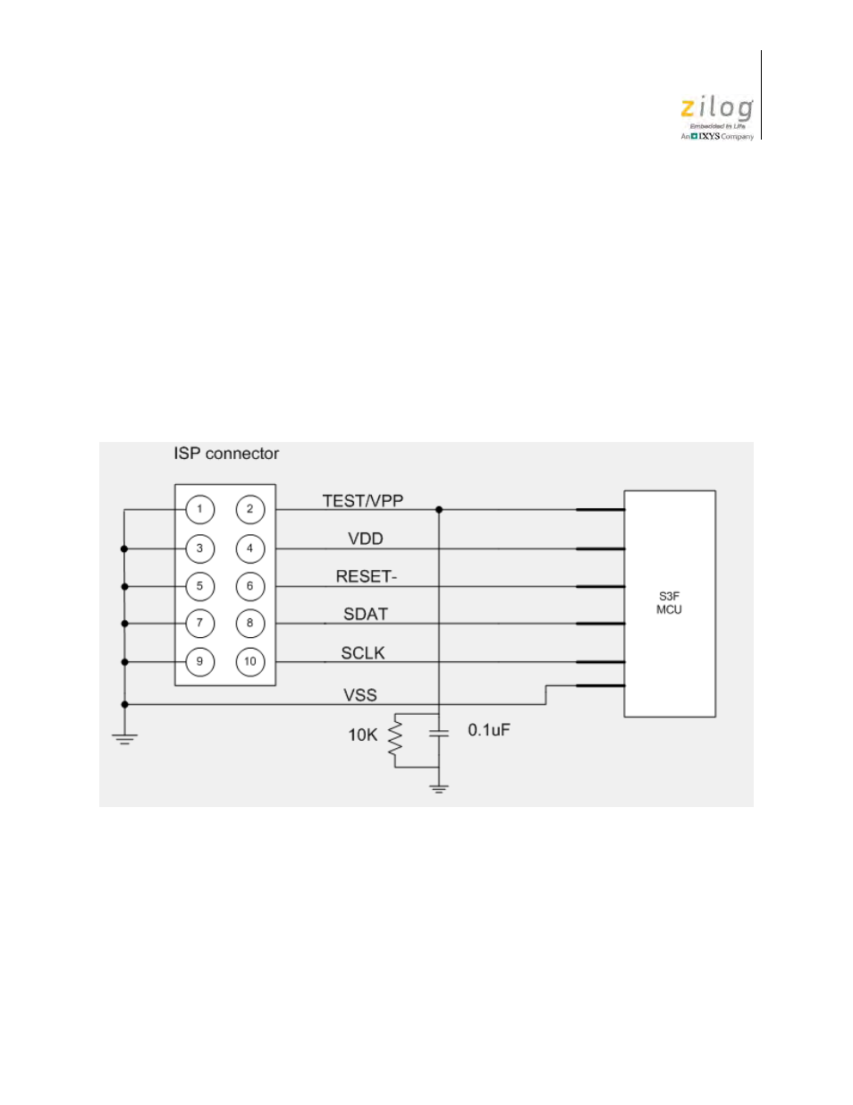
Figure 2 shows the connections between the ISP connector and the S3 Flash MCU. When
connecting the ribbon cable to your target board, ensure that you align Pin 1 of the cable
with Pin 1 of the connector on the board.
ISP Interface
The S3 Flash ISP interface consists of the following signals:
TEST/V
PP
.
Test Mode signal; when driven High, this signal places the S3 Flash MCU into
Test Mode to make on-chip Flash memory available for access by the S3 Flash ISP. Ensure
that you place a 0.1 µF capacitor and 10KOhm resistor between this pin and Ground, as
shown in Figure 2.
Figure 2. Target ISP Connector Interface