Neutrino series - quick start guide – Xilica Neutrino Series User Manual
Page 4
Neutrino Series -
Quick Start Guide
XILICA AUDIO DESIGN CANADA / ASIA / EUROPE
Pag
e
4
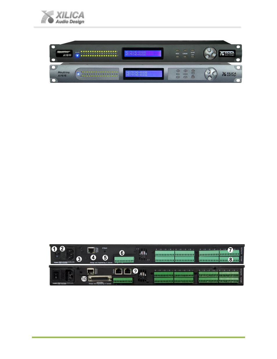
5. Hardware:
FRONT PANEL
Top - front panel of Neutrino A1616 model shown (older front panel version shown below it)
1.
LCD Display
The LCD Display shows all of the necessary information to control the settings of the unit from the front panel.
2.
Power Status LED
(New front panel version only)
3.
Network Status LED
(Data Status LED on older front panel version)
When the processor has an Ethernet cable / network cable connected the Network status LED on the front of the
processor will light - once the processor initializes. If there is no Ethernet / network cable attached it remains off.
Note:
When the Network status LED is on it does not mean that you have established a Network Connection
– only
that an Ethernet or network cable is connected to the processor. Proper Network Connection and Operation is
indicated/displayed only in the software’s “Network View” page (see the Network View & Connection section of this
guide).
When the processor and software are connected and communicating the Network status (Data status) light will flash.
4.
Input/Output Signal Indicators
Each Input and Output channel has a dual colour LED signal indicator. Green for signal present at -40 dBu and
Red at +17 dBu at the advent of analog clipping.
5.
Menu Buttons
There are 6 menu keys: <
<
Go to previous menu screen.
Menu
>>: Go to next menu screen.
<
Go to previous cursor in the menu screen.
Cursor>>:
Go to next cursor in the menu Screen.
Enter:
Enter enters the System Menu from the main menu and is used in the System Menu to proceed with
selected actions.
Exit
: Exit to the Main Menu.
REAR PANEL
Rear panel of Neutrino A1616 (top) and A1616-ND (bottom) models shown above
1.
Power On/Off Switch
2.
Fuse Compartment
Should you need to replace the fuse use a T2 5A-250v fuse. Ensure power to the device is disconnected when
replacing the fuse.