Neutrino series - quick start guide – Xilica Neutrino Series User Manual
Page 15
Neutrino Series -
Quick Start Guide
XILICA AUDIO DESIGN CANADA / ASIA / EUROPE
Pag
e
15
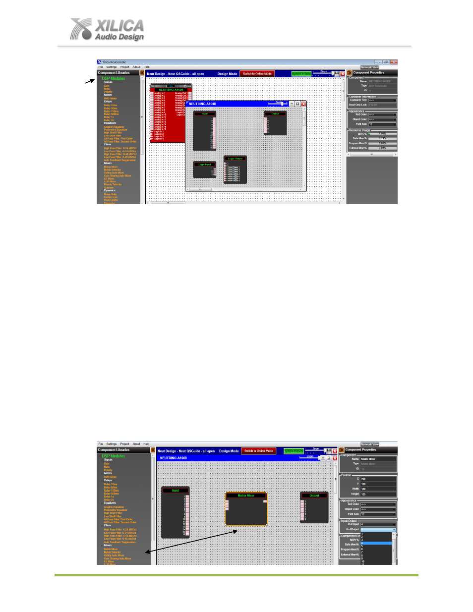
Processor Module
– DSP Schematic Design Page
(a) Double-Click on the red Neutrino A1608 processor module shown above to open it and to
access its DSP schematic design layout page
– defined by a grey dotted work area (not
white).
(b) The DSP schematic design page
has ‘Input’, ‘Output’ and ‘Logic’ DSP modules already
inserted and shown by default.
(c) Notice that once you
’ve opened up the Neutrino DSP module to display the DSP schematic
design page that under the Component Libraries at the left
– the list of
System
Components
has been replaced by
DSP Modules
. DSP modules that can be dragged and
dropped into the DSP schematic design page to create your DSP design schematic.
16. NeuConsole Software -
Creating Your DSP Design Schematic:
For this design example, we will create a very simplistic speaker crossover DSP schematic.
(a) Enlarge the opened, grey dotted DSP Schematic design page, move the Input and Output
DSP modules to the left and right and the two logic modules out of the way (since we will not
be using them this time) to create a larger DSP schematic work area
– as shown below.
(b) As shown below - under
DSP Modules
on the left - drag and drop a Matrix Mixer onto the
schematic design work area. (Click on the grey dotted DSP schematic design page to open
the Components Library and the list of DSP modules if it is temporarily hidden).