Wiring diagram, Ignition control – Dayton 5S1792 User Manual
Page 21
21
Models 2E510F, 2E511F, 3E218E, and 3E219E
Dayton Operating Instructions and Parts Manual
105553
®
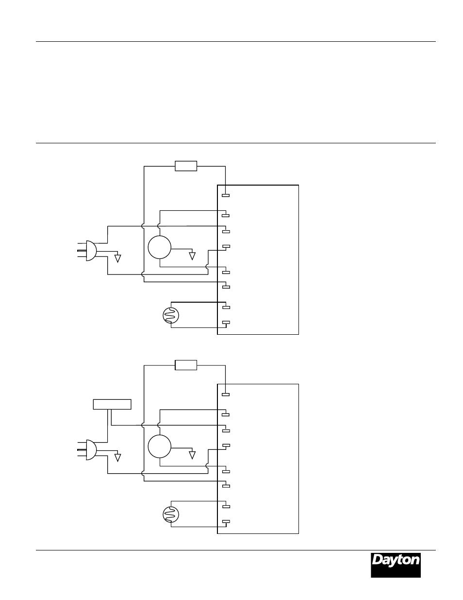
Wiring Diagram
Figure 36 - Wiring Diagram, Models 2E510F and 2E511F
Blue
Photocell
Power Plug
120V/60Hz
Ignitor
Ignitor
Blue
White
Red
Green
Motor
White
Black
Gray
Gray
Photocell
Photocell
Ignitor
Motor Return
120V (L1)
Motor Main
AC Neutral (L2)
Ignition Control
Green
Blue
Photocell
Power Plug
120V/60Hz
Ignitor
Ignitor
Blue
White
Red
Yellow
Yellow
Green
Motor
White
Black
Black
Photocell
Photocell
Ignitor
Motor Return
120V (L1)
Motor Main
AC Neutral (L2)
Thermostat
Ignition Control
Green
Figure 37 - Wiring Diagram, Models 3E218E and 3E219E