ThunderMax PN#309-362 - FL Touring Models User Manual
Page 2
www.Thunder-Max.com
309-362 Installation / Setup Guide V2013.10.15
2
FL-D:
.
Route
the
rear
sensor
lead
between transmission
top cover and the
starter, then towards
the
ABS
caddy
located
under
the
right
side
cover.
Place
the
sensor
connector under the
ABS caddy.
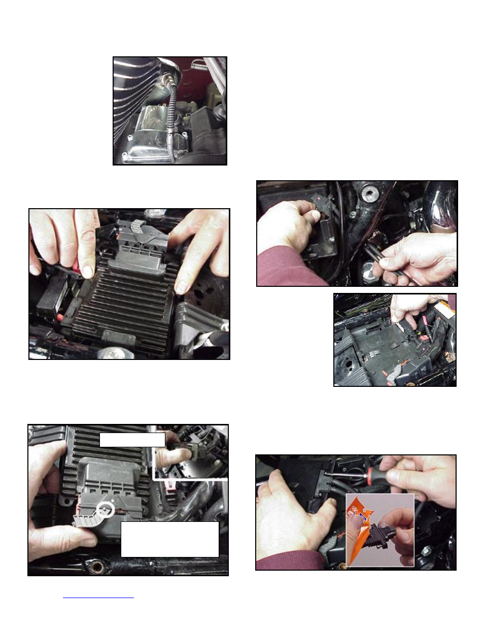
FL-E:
Remove factory ECM from the caddy by
spreading the plastic caddy latches at the sides of the
ECM. Lift the ECM up and to the right to release it from
the caddy.
FL-F:
Disconnect the ECM from the connector as per
the following procedure:
Depress button on socket housing of the connector;
rotate locking bar until it reaches the full rearward
position (the index pin on locking bar will engage the
rear notch in the socket housing).
The connector internal latches are not fully disengaged
until the locking bar on the connector is seated to the full
rearward position to complete removal of the connector.
If you force the socket housing with latches partially
engaged, it will result in damaging the connector. Once
index pin is fully seated, with steady yet careful attention,
pull apart the connector from the factory ECM and
remove it from the motorcycle.
FL-G:
With the factory ECM removed, route the
AutoTune harness thru the opening on right side of the
frame below the down tube for the seat, towards the
ECM caddy.
FL-H:
. If equipped
with factory alarm,
detach
alarm
antenna from ECM
caddy clip by lifting
slightly and sliding
to the right of bike
(do not disconnect).
FL-I:
Locate the package of dielectric grease included
with communication cable. Spread a small amount of
grease on the AutoTune harness plug inboard of the
mounting flange to allow the plug to easily slide into the
ThunderMax ECM, with ThunderMax logo on harness
plug facing up. Attach with screws provided.
FL-J:
Install main harness connector to ThunderMax
Depress button
Rotate locking bar fully
towards rear of bike until
index pin reaches notch