Nstallation – OT Systems ET2111 series User Manual
Page 9
ET2111 Series Installation & Operation Manual
9
3.5 Installation
This chapter gives step-by-step instructions about how to install the switch:
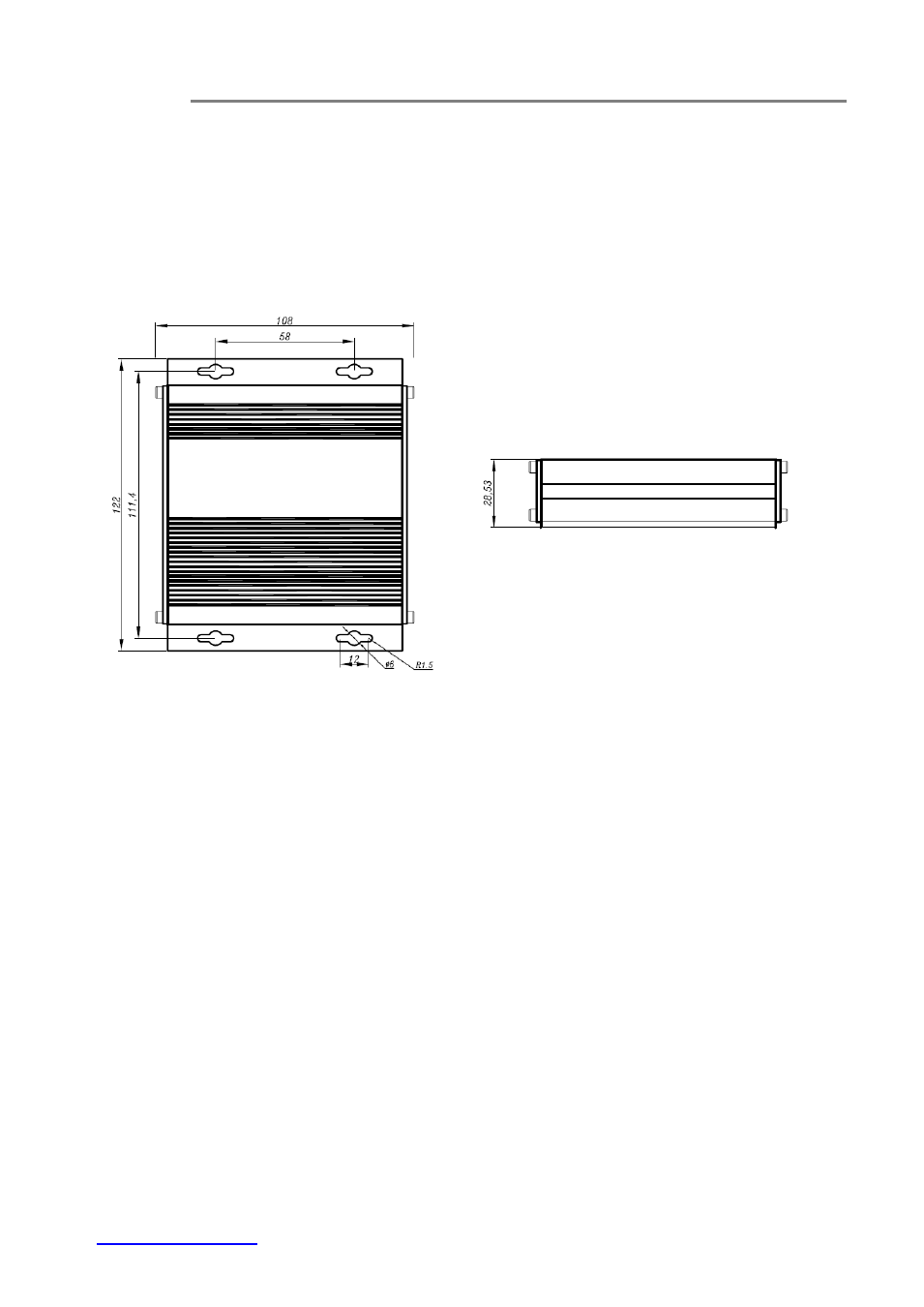
3.5.1 Standalone wall mount type
a) Mount the ET2111 onto a fixture or camera housings, e.g. a plank, (either on the
wall or on a flat surface) with four screws through the holes on the mounting
frame to secure it in position.
(a) Top view
(b) Side view
Fig. 3.5 Dimension of Micro type units
b) The power supply should also be mounted on the same fixture or in the proximity
for connection of the supply cables to the unit, provided that an AC power supply
socket is nearby for powering the adaptor.
c) Connect all the signal inputs and outputs at the unit with appropriate cables: fiber
optic cable for optical link and UTP/STP Cat 5 cable for Ethernet. Please refer to
Section 4.1 for the details.
d) Once the unit is powered up, check that the POWER LED on the unit is lit. If not,
check the power supply cable connections between the unit and the power
supply socket.
e) With all the signals available at the physical ports, check the status of LEDs
located on the unit. With correct status of each LED, installation is now completed
[for LEDs status, see Operational Guides
on this manual’s Section (5)].