Rack installation, Setup, Interface – OT Systems ET24122MPp-S User Manual
Page 6: Ethernet port rj-45 pin assignment
ET24122MPp-S
24-port 10/100Base-TX + 2-port 10/100/1000Base-T/SFP Combo Managed PoE Ethernet Switch
V1.1
6
Rack Installation
ET24122MPp-S can be installed on a rack. The product has 4 mounting holes. Use 4 rack mount screws
to securely install the product in a 19” rack cabinet.
Setup
a) Connect the Ethernet port of the optical Ethernet switch to be used to a PC or network device with a
network cable.
b) Insert the appropriate SFP into the corresponding SFP port. Connect the fiber cable from the remote
device (media converter or switch) to the LC connector of the SFP.
c) After the device is powered on, the PWR indicator will all be on. If the indicators are not on, check the
power supply connection.
d) After all cables are correctly connected, the indicators will be lit as per port status LEDs (page 4).
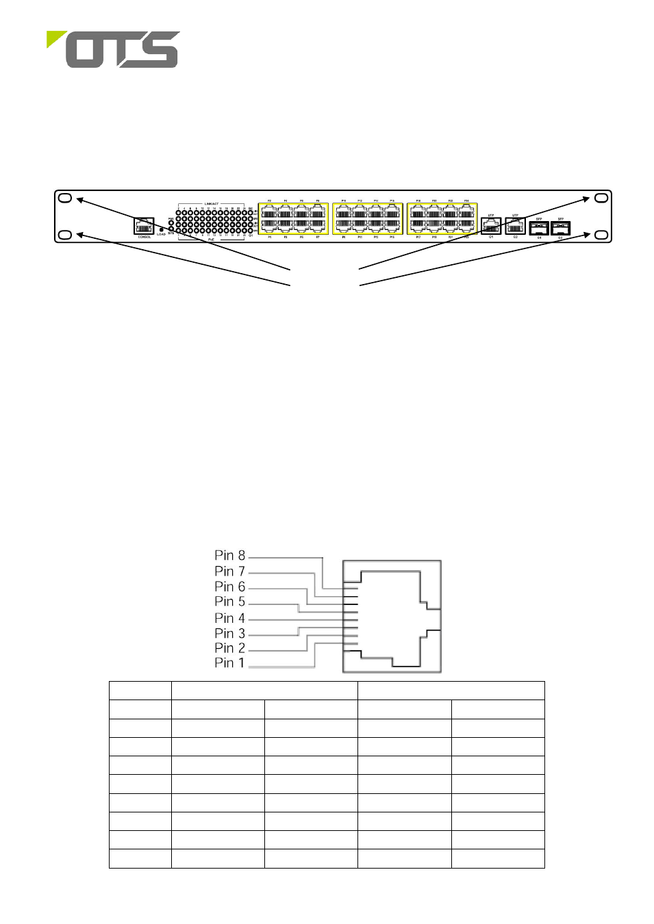
Interface
Ethernet Port RJ-45 Pin Assignment
10/100Base-T Pins
1000Base-T Pins
Pin
MDI
MDIX
MDI
MDIX
1
TD+
RD+
TP0+
TP1+
2
TD-
RD-
TP0-
TP1-
3
RD+
TD+
TP1+
TP0+
4
Positive (VCC+)
Positive (VCC+)
TP2+
TP3+
5
Positive (VCC+)
Positive (VCC+)
TP2-
TP3-
6
RD-
TD-
TP1-
TP0-
7
Negative (VCC-)
Negative (VCC-)
TP3+
TP2+
8
Negative (VCC-)
Negative (VCC-)
TP3-
TP2-
Mounting
Holes