Mcu com port (jp3), Serial-ata power input (cn9, cn11, cn14, cn16) – NEXCOM nROK 5300 User Manual
Page 44
31
Chapter 2: Jumpers and Connectors
Copyright © 2012 NEXCOM International Co., Ltd. All rights reserved
nROK 5X00 Series User Manual
1
3
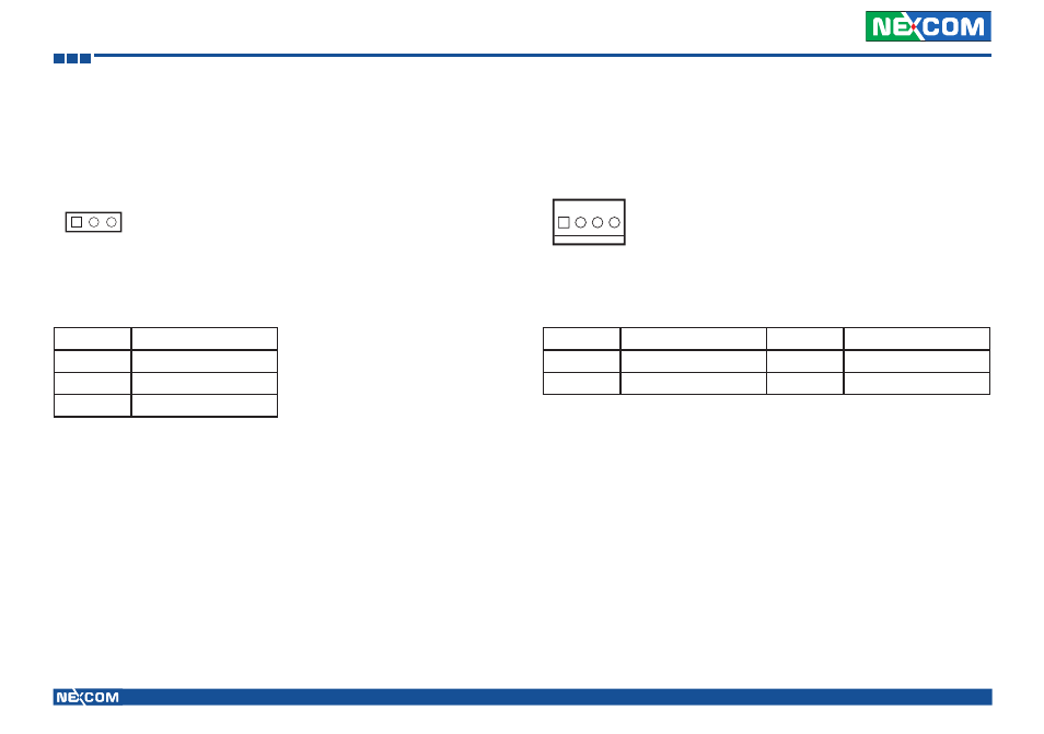
MCU COM Port (JP3)
A. Connector size: 1 x 3 = 3-pin header
B. Connector location:
Serial-ATA Power Input (CN9, CN11, CN14, CN16)
A. Connector size: 1 x 4 = 4-pin header
B. Connector location:
Pin
Definition
1
TX
2
RX
3
GND
Connector pin definition
1
4
Pin
Definition
Pin
Definition
1
VCC12
2
GND
3
GND
4
VCC5
Connector pin definition
This manual is related to the following products:
See also other documents in the category NEXCOM Hardware:
- EBC 352 (68 pages)
- EBC 353 (62 pages)
- EBC 355 (63 pages)
- EBC 354 (63 pages)
- ICES 268 (96 pages)
- ICES 667 (100 pages)
- ICES 254 (98 pages)
- NEX 604 (61 pages)
- NEX 608 (67 pages)
- ICES 668 (105 pages)
- NEX 607 (75 pages)
- NEX 609 (61 pages)
- NEX 611 (51 pages)
- NEX 613 (45 pages)
- NEX 617 (53 pages)
- NISE 101 (79 pages)
- NISE 104 (78 pages)
- NISE 2020 (84 pages)
- NISE 105A (78 pages)
- NISE 103 (83 pages)
- NISE 2110A (87 pages)
- NISE 2420 (84 pages)
- NISE 301 (74 pages)
- NISE 2310E (107 pages)
- NISE 2210E (110 pages)
- NISE 3100eP2 (75 pages)
- NISE 300 (95 pages)
- NISE 3140P2E (88 pages)
- NISE 3520P2E (125 pages)
- MAC 3500P2-GTS8 (120 pages)
- NISE 3600E (102 pages)
- NISE 3720P2E (85 pages)
- NISE 3640P2E (105 pages)
- NISE 3640M2E (108 pages)
- NISE 4000 (102 pages)
- nTUF 600 (100 pages)
- NEX 716VL2G (71 pages)
- NISE 4000P4E (128 pages)
- NISE 4000P2E (131 pages)
- NEX 732L2G (71 pages)
- NEX 883 (53 pages)
- NEX 890 (58 pages)
- NEX 980 (52 pages)
- NEX 852VL2 (62 pages)
- NEX 981 (47 pages)