Connector pin definitions, External i/o interfaces - front panel, Usb 3.0 displayport a – NEXCOM NISE 3600E User Manual
Page 28: Usb 3.0, Displayport a
Copyright © 2012 NEXCOM International Co., Ltd. All Rights Reserved.
14
NISE 3600E Series User Manual
Chapter 2: Jumpers and Connectors
Connector Pin Definitions
External I/O Interfaces - Front Panel
USB 3.0
Connector type: Dual USB 3.0 ports
Connector location: USB1
Pin
Definition
Pin
Definition
1
VCC5
2
USB2_2N
3
USB2_2P
4
GND
5
USB3_RX2_N
6
USB3_RX2_P
7
GND
8
USB3_TX2_N
9
USB3_TX2_P
10
VCC5
11
USB2_3N
12
USB2_3P
13
GND
14
USB3_RX3_N
15
USB3_RX3_P
16
GND
17
USB3_TX3_N
18
USB3_TX3_P
MH1
GND
MH2
GND
MH3
GND
MH4
GND
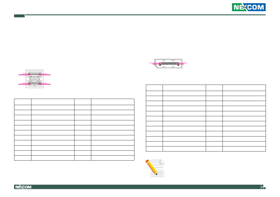
DisplayPort A
Connector type: DisplayPort
Connector location: J10
Pin
Definition
Pin
Definition
1
DPC_LANE0_P
2
GND
3
DPC_LANE0_N
4
DPC_LANE1_P
5
GND
6
DPC_LANE1_N
7
DPC_LANE2_P
8
GND
9
DPC_LANE2_N
10
DPC_LANE3_P
11
GND
12
DPC_LANE3_N
13
DPC_CONFIG1
14
DPC_CONFIG2
15
DPC_AUX_P
16
GND
17
DPC_AUX_N
18
DPC_HPD
19
GND
20
VCC3
MH1
GND
MH2
GND
MH3
GND
MH4
GND
While using DisplayPort to HDMI cable or DisplayPort to DVI
cable, the cable must be active type.
9
1
5
4
10
13
14
18
2
1
19
20