Operation – Monroe Electronics Electrostatic Voltmeter - Isoprobe® - model 244A User Manual
Page 13
13
SECTION 4
OPERATION
CAUTION:
Verify that instrument operating voltage matches local power line voltage. Refer to
Section 2.
PRECAUTIONARY NOTE
Model 244A is a non-contacting voltmeter. The potential of the probe will attempt to
follow the potential of any object within the field of view of the sensitive electrode (up to
±3400 volts) when the instrument is operating. In the interest of operator safety and also
to reduce high voltage stress within the instrument, it should be left in the STANDBY
mode whenever it is not being used and particularly when the probe will not be "looking"
at a surface of less than 3000V.
A. INITIAL SET-UP:
1.
With PROBE mounted as previously described in Section 2, connect
probe plug to the probe receptacle on the instrument front panel.
2.
Switch STANDBY/OPERATE switch to OPERATE.
3.
Set RESPONSE SPEED (GAIN) control according to the probe-to-sur-
face spacing and desired speed-of-response. In the event the front panel
meter is the sole indicator of the instrument output, the normal static error
is very small and speed-of-response is non- critical. For
1
/8" (3mm)
spacing, set at
½
of CW rotation.
NOTE:
Decreasing the probe-to-surface spacing has the same influence as increasing
the GAIN control. The GAIN control should, therefore, be re-adjusted whenever
the probe-to-surface spacing is altered if optimum speed-of-response is desired.
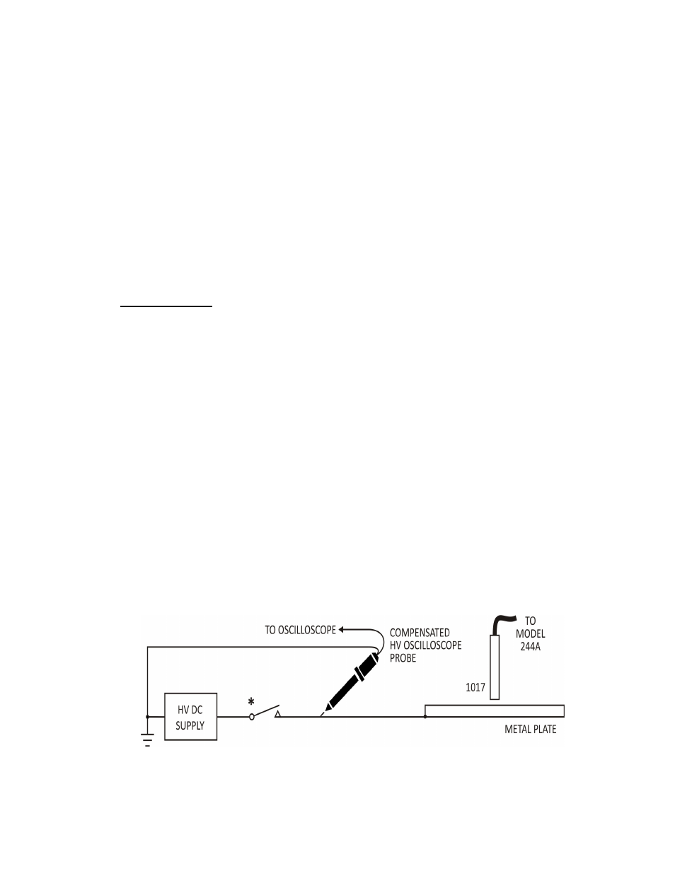
a. Connect a DC supply through a switch to a metal plate at the same
probe-to-surface spacing to be utilized (preferably the same surface if
practicable) as shown in FIGURE 4-1.
F
I
G
U
R
E
4
-
1
* Switch with low contact bounce - preferably H.V. Reed Relay Contact
b.
Connect the OUTPUT to a recorder or scope.