KBC Networks WESIIKT V221 17dBi to 17dBi Kit User Manual
Page 3
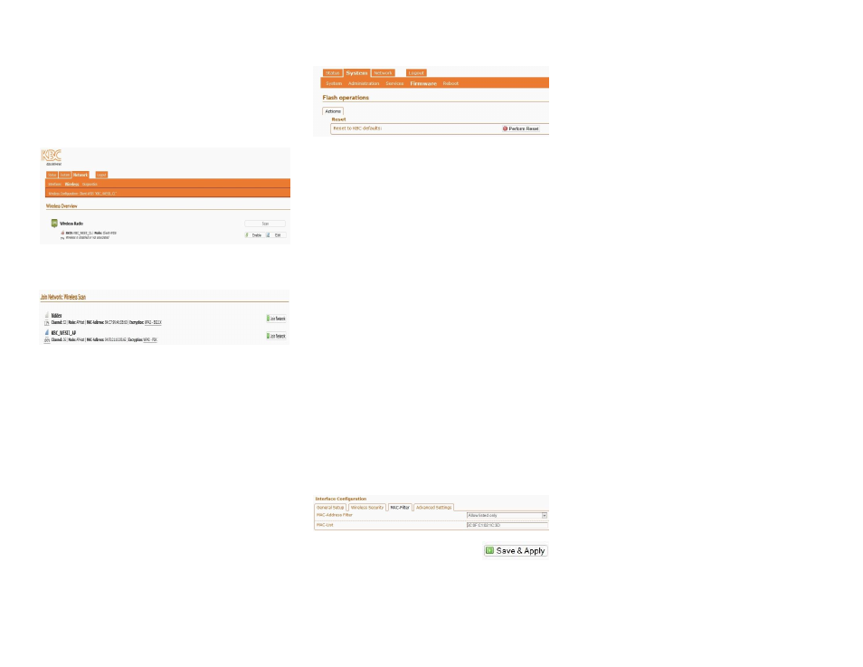
Configuring the Client unit:
8.
If you have made any changes to the AP-
Host SSID, encryption or pre-shared key
then you will need to re-join the Client to
the new APHost “network”.
9.
Follow steps 1-5 above this time using
192.168.1.201 for the default Client IP.
10.
Click on “Network” then “Wireless” and
click “Scan”
11.
Select your Host from the list of Access
Points. And enter the unit pre-shared key
to connect to it.
Note:
Allow up to 2 minutes for the units to
connect to each other.
Note:
Record all changes and details. MAC
addresses, custom IP addresses, SSIDs and/or
pre-shared keys and such detail needed for the
units to link which are not kept on file will
require a hard reset. Resets performed in the
factory are subject to a non-warranty repair
charge.
Reset to Default Settings
Via Interface:
1) Click on “System” then “Firmware”
2) Click on "Perform Reset”
Via External Reset Button:
The WESII can also be hard reset from the
button on the underside of the case.
1) Power up the WESII APHost or Client RF
module and allow it to go through its
reboot process.
2) Remove the phillips head screw (be sure
to replace it when complete).
3) Insert a small screwdriver in order to push
the reset button.
4) Hold the button for approximately 10
seconds and release.
5) Ensure that your computer is set to the
192.168.1.x subnet and the unit will be
accessible on the configurations shown in
the section below.
Note:
The LEDs will not light up or flash during
the reset process.
Note:
A restore to defaults will erase custom
configuration settings and disable the MAC
lock feature.
Re-Locking the Host to its Client MAC:
From the Status page, click on the blue SSID
which will take you to the configuration page.
1) Click on “MAC-Filter”
2) Select “Allow Listed Only”
3) Enter the Client’s Radio 1 MAC address.
4) Click “Save & Apply”
5) Perform steps 1-4 on the Client side,
entering the APHost Radio 1 MAC there.
WESII Status Indicators (Left to Right)
1.
Status/Signal Strength Indicator
In power up / boot up process
40+ RSSI
RSSI less than 40 (or no link if the
other RSSI LEDs are not on)
2.
Signal Strength Indicator
Solid green 30-39 RSSI
RSSI less than 30 (or no link if the
other RSSI LEDs are not on)
3.
Signal Strength Indicator
20-29 RSSI
RSSI less than 20 (or no link if the
other RSSI LEDs are not on)
4.
Signal Strength Indicator
10-19 RSSI
RSSI less than 10 (or no link if the
other RSSI LEDs are not on)
5.
Network – Ethernet link activity
Link activity established
Link activity from WESII to
connected Ethernet device or across
wireless link.
No link to Ethernet cable connected
device. (not indicative of wireless
link/strength)
6.
Power
Power applied.
No power to unit. Ensure that the
power injector and power supply is being
used. These units will not power directly
from a POE switch.
Flashing LED
Solid LED
LED off
Note:
The LEDs do not change colors.
1
2
1
2
3
4
10
11a
11b