Sheet4, Drawing view5, Drawing view118 – Future Automation PLH User Manual
Page 4: Drawing view120, Drawing view121, Drawing view126, Detail view a (1 : 5), Future automation plh, Stage 2, Plasma lift hinge mechanism instruction sheet
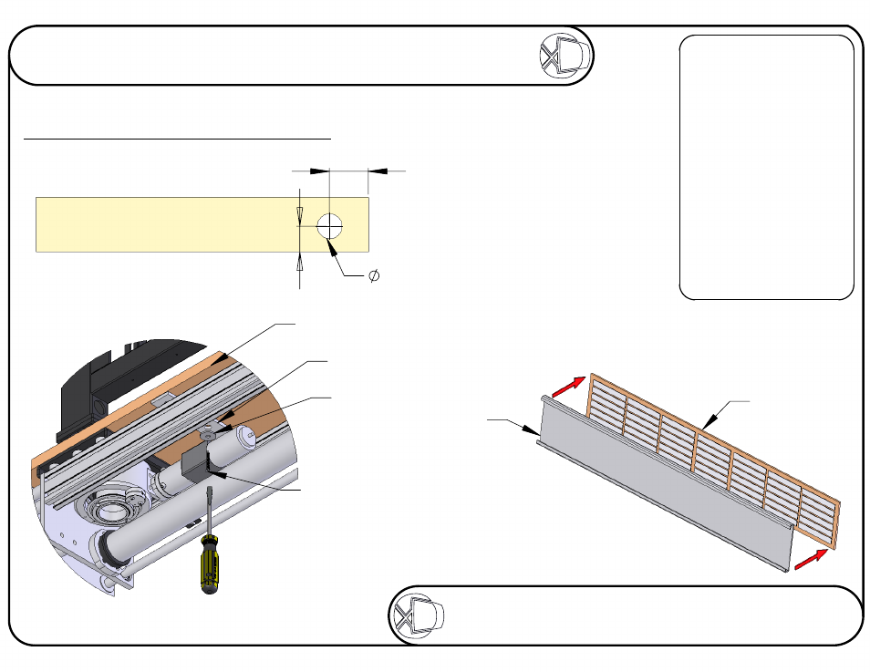
Aluminum
Flap
6mm Flap
125
107
80
A
DETAIL A
SCALE 1 : 5
Remove mount and place base
central onto the beam into position
and reattach the mount.
Fix the base by using penny washers
and wood screws through the
base supports
provided as
shown in
Detail A
Woodscrew
Penny
Washer
Base
Base
Supports
Stage 2
Fitting Flap And Base To Mechanism
FIXING
Make sure the base panel
lines up squarely, directly
on top of the lifting beam.
Consult
PLH TECHNICAL SHEET
before fabricating any
flaps or base panels.
The hole is necessary for hinge pole to pass through.
The 6mm flap and the base should be
made as part of the cabinet.
The surface of the flap should be
varnished or painted to prevent warping.
Take care when fixing the surfaces
together. Place the objects on a
flat surface to make sure the edges
are properly aligned when they
come into contact.
Try to use as many self
adhesive pads as possible
to get the most secure fixture.
VIEWING SIDE
Sheet 3 of 17
ISSUE: 006
www.futureautomation.co.uk
FUTUREAUTOMATION
PLH
Plasma Lift Hinge Mechanism
Instruction Sheet