Assembly – d&b Z5409 Horizontal bracket 10S 12S User Manual
Page 6
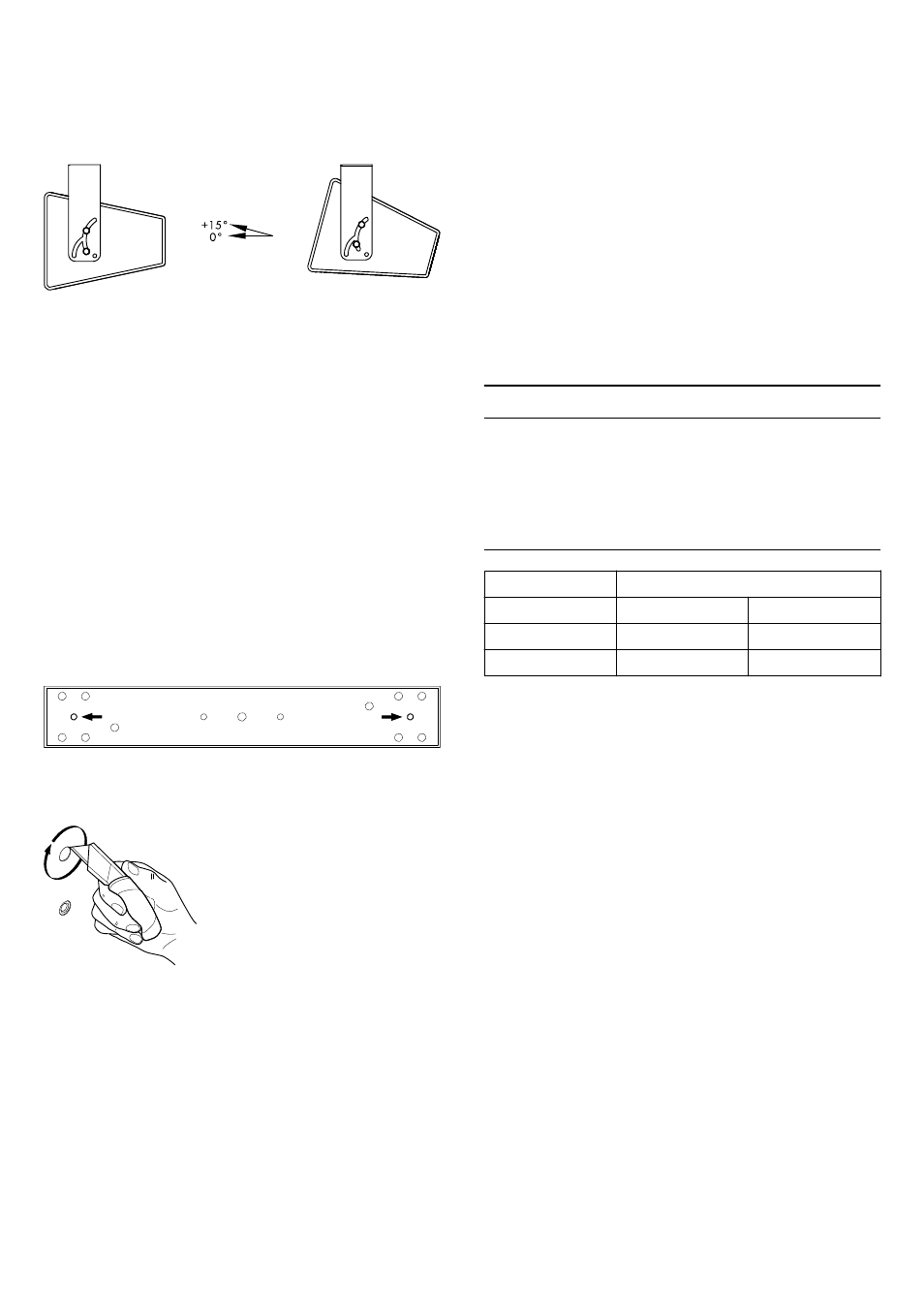
Option 3
The bracket is attached to the cabinet with hole
[a] facing to the
back of the cabinet. Both bolts are fitted into slot
[b].
The vertical coverage angle can be set over a range of 15°
starting from 0° to +15°.
1.5. Assembly
Attaching the bracket to walls or ceilings
NOTICE!
Only use mounting parts (fixing anchors and screws) that are
suitable for the intended application.
Observe the occurring extraction forces acting on the fixing
anchors and screws. The rated extraction forces for the respective
application (wall or ceiling mounting) and cabinet are listed in the
following table.
Application
Rated extraction forces
10S
12S
Wall mounting
250 N
300 N
Ceiling mounting
150 N
200 N
To attach the bracket to walls or ceilings, use the holes shown in
the graphic opposite to provide adequate support.
A corresponding fixing template is supplied with these mounting
instructions. Refer to Þ Chapter 2. "Fixing templates"
Preparing the cabinet
The top and bottom panels of the loudspeaker cabinet are each
equipped with a pair of M10 threads. The threads are covered by
dummy caps in cabinet color.
To remove the caps, proceed as follows:
1.
Cut out the caps along the recessed spline using an
appropriate cutting knife.
2.
Carefully take off the caps and ensure the cabinet coating is
not peeled off.
d&b Z5409/11 Horizontal bracket 10S/12S, Mounting instructions (1.2 EN)
6